WiFi
Wi-Fi is used for connecting various devices wirelessly to the internet or to each other. This includes computers, smartphones, tablets, smart home devices, and more. It uses radio frequencies to send signals between devices and a router, which then connects to the internet.
What is the Wi-Fi Spectrum
The Spectrum: radio spectrum from 3Hz to 3Thz (3000 GHz)
The Wi-Fi spectrum refers to the specific bands of radio frequencies that Wi-Fi operates within. These bands are portions of the electromagnetic spectrum that have been designated for unlicensed use by Wi-Fi and other wireless communication technologies.
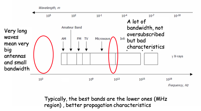
humans hear signals in 20-20 kHz range.
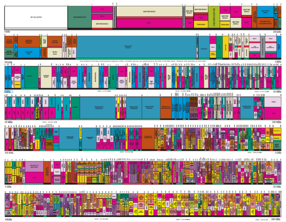
The spectrum has been allocated up to 300 GHz
The Spectrum
- Best bands are the lower ones (MHz region), better propagation characteristics
- Lower frequencies larger antennas
- There is plenty of bandwidth at very high frequencies but bad propagation characteristics
- A large part of the spectrum has been allocated a long time ago and sometimes to services or incumbents that are obsolete but try to hold their share of the spectrum
- Hence, the spectrum is not always well used and re-allocation is often necessary
- Spectrum is scarce resource and hence, it is heavily reused.
- For example, many WiFi networks in a building might use the same channel or in a cellular network, the same band is reused often in every cell. This creates interface. Interference management and spectrum reuse are critical problems in wireless.
Two Types of Bands:
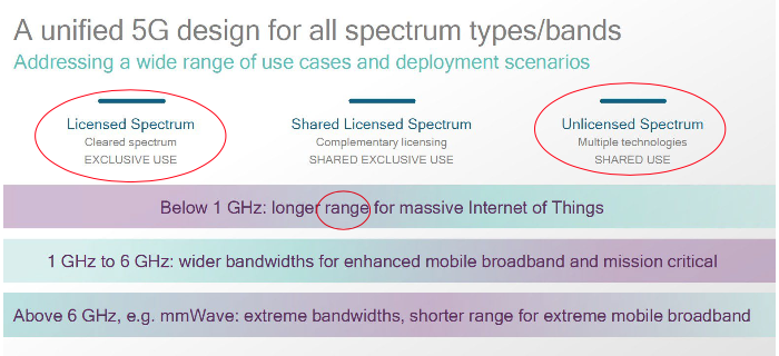
- Licensed: used by cellular networks
- Unlicensed: used by WiFi (and recently also by cellular networks)
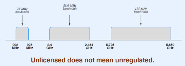
ISM Wireless Bands:
- ISM stands for Industrial, Scientific, and Medical
- Region of the electromagnetic spectrum available for use without license
- Used for wireless LANs and PANs (e.g., cordless phones)
- Four separate bands (a new one has been added by the FCC at 60 GHz, with complex sharing schemes to avoid incumbents)
3 Key Words
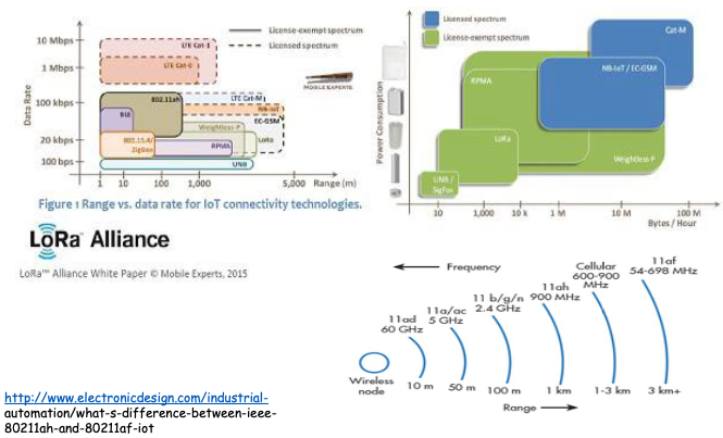
- Rate
- Range
- Power consumption
Qualcomm’s view of spectrum
The IoT of spectrum
Wireless link characteristics
- half-duplex: Typically a node cannot send and receive at the same time
- decreased signal strength: radio signal attenuates as it propagates through matter (path loss). Signals at some frequency do not cross walls…
- interference from other sources: ISM bands (e.g., 2.4 GHz) shared by other devices (e.g., phones); devices (motors) interfere as well, interference also occurs in licensed band due to reuse.
- multipath propagation: radio signal reflects off objects ground, arriving at destination at slightly different times … make communication across (even a point to point) wireless link “difficult”.
Characteristics depend on the band and are time-varying!
- SNR: signal-to-noise ratio
- larger SNR - easier to extract signal from noise (a “good thing”)
- SNR (Signal-to-Noise) vs. BER (Bit Error Rate) tradeoffs
- given physical layer: increase power increase SNR decrease BER
- given SNR: choose modulation and coding scheme that meets BER requirement, giving highest throughput
- SNR may change with mobility: dynamically adapt physical layer (modulation technique, rate)
This ignores interference!!! By increasing power, you increase interference.
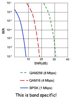
- graph shows the bit error rate (BER) as a function of the Signal-to-Noise (SNR).
- Different lines represent different modulation techniques such as BPSK (Binary Phase Shift Keying), QAM16, QAM256.
- These plots illustrates how more complex modulation schemes can carry more data but require higher SNR to maintain the same error rates.
Multiple wireless senders, receivers create additional problems (beyond multiple access):
- Hidden terminal problem:
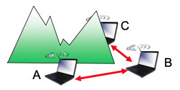
- B, A hear each other
- B,C hear each other
- A, C cannot hear each other means A, C unaware of their interference at B
- Signal attenuation:
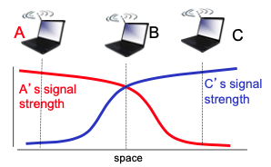
- B, A hear each other
- B, C hear each other
- A, C can not hear each other interfering at B
Cellular vs. Wi-Fi
- Cellular: wide area coverage, proprietary networks, more coordination between BSs.
- WiFi: local area coverage, “last link” for the Internet, little coordination between APs
- Cellular: licensed (and expensive) spectrum
- Wi-Fi: unlicensed (free) spectrum (2.4 GHz and 5.3 GHz)
- Cellular: high mobility
- Wi-Fi: low or no mobility
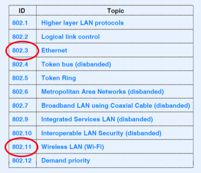
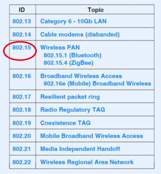
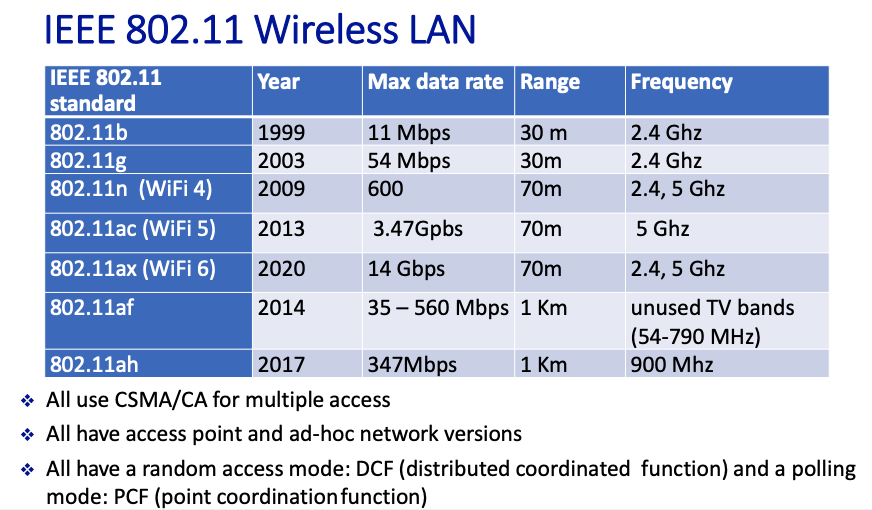
IEEE Standards:
802.11: Channels
- Different bands
- A band can be divided in channels of certain width.
- For example: 802.11b: 2.4 GHz-2.485 GHz band divided into I 4 channels at different frequencies (more on that next slide)
- AP admin chooses channel for AP
- Interference possible: channel can be same as that chosen by neighbouring AP
Summary
- IEEE 802.11 Standards Overview: This includes various Wi-Fi standards such as 802.11a/b/g/n/ac/ax, each offering different speeds, ranges, and frequencies. For instance, 802.11n (Wi-Fi 4) operates on both 2.4 GHz and 5 GHz bands, while 802.11ac (Wi-Fi 5) operates only on 5 GHz.
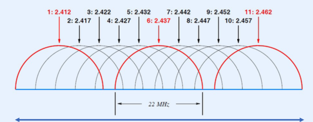
- Channel Allocation: Explains how the spectrum is divided into channels and the spacing between them. In the 2.4 GHz band, channels are typically 22 MHz wide with certain channels like 1, 6, and 11 being non-overlapping in many regions, reducing interference.
Practical Considerations: WiFi Channels
- I 4 channels (22 MHz) defined for North America in 2.4 GHz range
- Bad news: 22 MHz band
- Good news: channels I, 6, and I I can operate simultaneously with no interference
5 GHz Band:
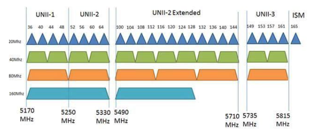
There are 24 non-overlapping 20MHz channels at 5GHz
IEEE 802.11 LAN Architecture
- wireless host communicates with access point (AP)
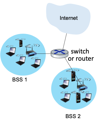
- Basic Service Set (BSS) (aka “cell”) in infrastructure mode contains:
- wireless hosts
- access point (AP)
- There is an adhoc mode with no AP (not used much)
- Random access mode: DCF (distributed coordinated function) and a polling mode: PCF (point coordination function)
Summary
BSS (Basic Service Set): Refers to a group of devices using the same Wi-Fi network within a single coverage area, typically managed by a single access point.
SSID, MAC Addresses, and Channel Scanning: Discusses how devices identify and connect to networks based on SSID (Service Set Identifier) broadcast by access points, and how devices scan different channels to find the best signal.
802.11: channels, association
- At network administrator allocates a name (SSID) to each AP
- Arriving host must associate with an AP
- scans channels, listening for beacon frames containing AP’s name (SSID) and MAC address
- selects AP to associate with
- then may perform authentification
- then typically run DHCP to get IP address in AP’s subnet
More details:
- Channel Allocation and SSID:
- Each WiFi access point (AP) operates on a specific channel within 2.4 GHz or 5 GHz frequency bands. The network administrator assigns a unique identifier (SSID, or Service Set Identifier) to each AP to distinguish between multiple networks.
- Device scan for available networks by listening for beacon frames broadcasted by APs, which contain the networks’s SSID and its MAC address.
- Association Process
- Association is the process by which a wireless device (like laptop or smartphone) joins a Wi-Fi network
- The device scans the channels and selects an AP to connect to based on signal strength and possibly other factors (like network load or security settings)
- After selecting an AP, the device may need to authenticate, which is the process of verifying the identity of the device or user, often using a password or other security credentials
- Once authenticated, the device usually runs DHCP to obtain an IP address from the AP, enabling network communication
802.11: passive/active scanning
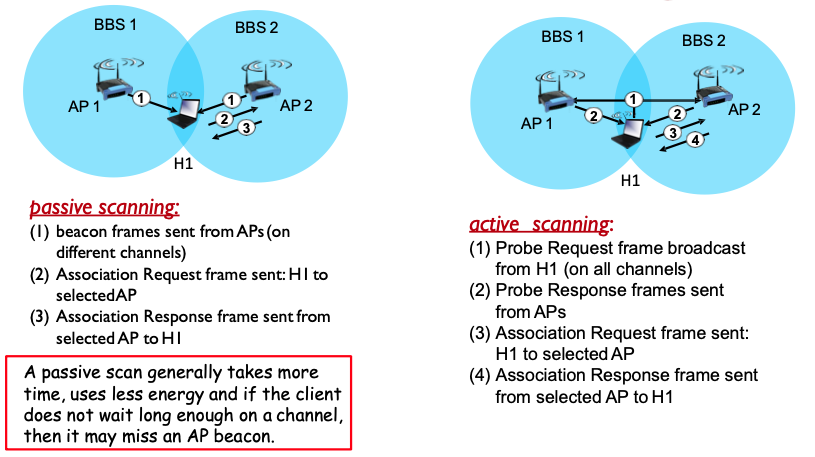
A passive scan generally takes more time, uses less energy and if the client does not wait long enough on a channel, then it may miss an AP beacon.
More details:
- Passive Scanning:
- In passive scanning, the device listens on each channel for beacon frames from APs without actively sending any data.
- This method is less energy-intensive and quieter in terms of radio frequency use because it does not transmit.
- However, it might take longer to find an AP, especially if the wait on each channel isn’t long enough to catch a beacon frame.
- Active Scanning:
- In active scanning, the device actively probes for networks by sending a probe request and listening for a probe response from APs.
- This method is faster because the device directly asks for responses from APs, but it uses more energy and might cause more radio frequency interference.
- It involves sending a probe request to each channel and waiting for a probe response from APs, followed by association requests and responses once a suitable AP is selected.
IEEE 802.11: DCF Mode (Random Access)
- 802.11: CSMA - sense before transmitting
- don’t collide with ongoing transmission by other node
- 802.11: no collision detection!
- difficult to receive (sense collisions) when transmitting due to weak received signals (fading)
- cannot sense all collisions in any case: hidden terminal, fading
- goal: avoid collisions: CSMA/C(ollision)A(voidance): two CA mechanisms (one compulsory and one optional).
- Unlike Ethernet, Wi-Fi devices cannot detect collisions while transmitting. Instead, they attempt to avoid collisions by employing a random backoff time if the channel is busy, which is decremented as long as the channel is sensed idle.
IEEE 802.11 MAC Protocol: CSMA/CA
802.11 sender
- if sense channel idle for
DIFSthen transmit entire frame (no CD) - if sense channel busy then start random backoff time timer counts down while channel idle. Then go to 1 when timer expires
802.11 receiver
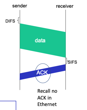
- if frame received OK
- return ACK after
SIFS<DIFS(ACK needed due to hidden terminal problem and bad channel conditions)- SIFS < DIFS (because we prioritize ack over other transmissions)
- return ACK after
- if no ACK, after timeout, increase random backoff interval, try again to transmit starting at the beginning of the process. Try a maximum of 7 times.
First CA mechanism (compulsory) DIFS/SIFS, increasing backoff, ACK
Step-by-Step CSMA/CA Process for IEEE 802.11:
- DIFS (Distributed InterFrame Space):
- The sender waits for a period called DIFS, which is a short time interval ensuring the medium is idle.
- If the medium is detected as idle for the duration of DIFS, the sender proceeds to transmit the data frame.
- Backoff Timer:
- If the medium is busy, the sender initializes a random backoff timer. The sender continues to monitor the channel, and the countdown only occurs when the channel is sensed as idle.
- This random backoff helps reduce the chances of collision when multiple devices attempt to transmit immediately after the medium becomes idle.
- Transmission and ACK:
- Once the backoff timer expires and the medium is idle, the sender transmits the data frame.
- The receiver, upon successfully receiving the frame, sends back an acknowledgment (ACK) after waiting for a shorter interval called SIFS (Short InterFrame Space), which is less than DIFS to prioritize acknowledgments over other transmissions.
- Handling Non-Acknowledgment:
- If the sender does not receive an ACK within a specified timeout, it assumes that a collision or an error occurred.
- The sender then increases the backoff interval and retries transmission, up to a maximum of 7 attempts as a standard practice. This increasing backoff mechanism reduces the likelihood of consecutive collisions.
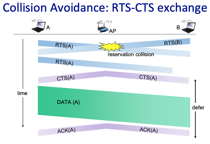
The RTS/CTS mechanism is designed to minimize collisions through a reservation-based system. It is particularly useful in scenarios where all devices cannot hear each other, commonly known as the “hidden terminal problem.
How RTS/CTS Works:
- RTS (Request to Send):
- Initiation: A sending device (let’s call it Device A) wants to transmit a data frame. Before sending the large data frame, it sends a short RTS frame to the access point (AP).
- Purpose: The RTS frame includes the sender’s address, the receiver’s address, and the duration of the time the sender needs to communicate, which helps in reserving the medium.
- CTS (Clear to Send):
- Broadcast by AP: Upon receiving the RTS, if the medium is free, the AP sends back a CTS frame after a short wait defined as SIFS (Short InterFrame Space).
- Content: The CTS frame also includes the duration field, indicating to all devices in the network how long the channel will be reserved for the sender.
- Effect: All nodes that hear the CTS will defer their transmissions for the duration specified, thus avoiding collision at the receiver.
- Data Transmission:
- Following the exchange of RTS and CTS, Device A sends its data frame to the AP or directly to another device if in an ad hoc network.
- Acknowledgment (ACK):
- After successfully receiving the data, the receiver sends an acknowledgment frame back to the sender, confirming the successful data reception.
802.11 Frame Addressing
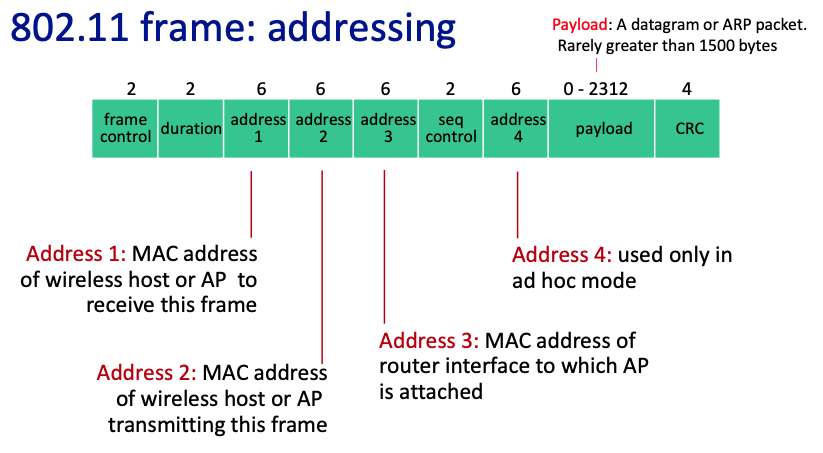
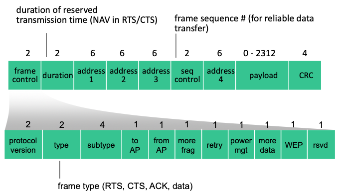
- Frame Control: contains protocol version, type, and subtype info that dictates how the rest of the frame is interpreted
- Duration: specifies the time (in ms) the channel will be reserved following this frame’s transmission, or an identification sequence
- Address Fields:
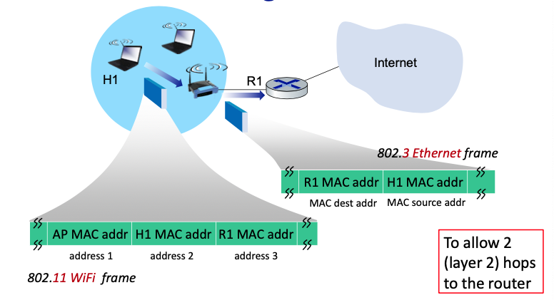
- Address 1: The receiver’s MAC address
- Address 2: The sender’s MAC address
- Address 3: The MAC address of the router or AP to which the sending device is connected
- Address 4: Used only in ad hoc mode, indicating the final destination when frames need to make more than one hop
- Sequence Control: contains a sequence number and a fragment number, used for ordering frame fragments correctly
- Frame Body (Payload): contains the encapsulated data. For data frames, this would typically be the IP packet or ARP message
- CRC (Cyclic Redundancy Check): a checksum used to ensure the integrity of the data included in the frame
802.11: advanced capabilities
Power management
- node-to-AP: “I am going to sleep until next beacon frame”
- AP knows not to transmit frames to this node
- node wakes up before next beacon frame (one beacon frame every 100ms)
- beacon frame: contains list of mobiles with AP-to-mobile frames waiting to be sent
- node will stay awake if AP-to-mobile frames to be sent; otherwise sleep again until next beacon frame (the wake up is 250 microseconds)
- a node with nothing to send or receive can sleep 99% of the time!
Summary
- Power Saving Mode: Nodes (like mobile devices) communicate to the access point (AP) their intention to sleep until the next beacon frame. Beacon frames are typically sent at fixed intervals (e.g., every 100ms) to synchronize the network.
- AP Behavior: When a node indicates it will sleep, the AP will not send data to that node until the next beacon frame. The AP also keeps track of which nodes are asleep and awake.
- Beacon Frames: These frames contain a list of nodes for which the AP has data waiting to be sent. When nodes wake up, they check the beacon frame to see if there’s data for them.
- Efficiency: Nodes can sleep for up to 99% of the time when they have no data to send or receive, significantly saving battery life.
802.15.1: personal area network (PAN)
PAN like Bluetooth.
- less than 10 m diameter (short range), low power, low rate, 2.4 GHz, up to 2Mbps
- 802.15.1: evolved from Bluetooth specification
- replacement for cables (mouse, keyboard, headphones)
- ad hoc: no infrastructure, 8 active devices at a time, 255 parked
- master/slaves: a node becomes master
- master rules, its clock determines time, transmit in odd-numbered slot (slot = 625 microseconds)
- slaves only transmit to master on even-numbered slot after being talked to
Summary
- Characteristics: Designed for very short-range communication (up to 10 meters), low power consumption, and relatively low data rate transmission (up to 2 Mbps).
- Evolution and Usage: Evolved from the Bluetooth specification and is widely used for connecting personal devices such as mice, keyboards, and headphones without the need for physical cables.
- Network Structure: Utilizes an ad hoc setup where up to 8 devices can be active at a time, with potentially 255 devices in a “parked” state (connected but not actively communicating).
- Communication Protocol: Involves a master-slave relationship. One device acts as the master using its clock to synchronize communications. Data transmission occurs in slots (625 microseconds each), with the master transmitting in odd-numbered slots and slaves responding in even-numbered slots.
