Processors
Controls the operation of the computer and performs its data processing functions. When there is only one processor, it is often referred to as the central processing unit (CPU).
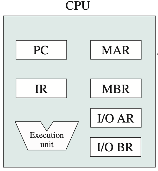
One of the processor’s functions is to exchange data with memory.
For this purpose, it typically makes use of two internal (to the processor) registers:
- a memory address register (MAR), which specifies the address in memory for the next read or write;
- a memory buffer register (MBR), which contains the data to be written into memory or which receives the data read from memory
- an I/O address register (I/OAR) specifies a particular I/O device
- an I/O buffer register (I/OBR) is used for the exchange of data between an I/O module and the processor.
Modern Processors:

- edge-triggered clocking
- combinational logic vs sequential circuits
- Registers
- Register File
- Arithmetic Logic Unit
- Multiplexors
- Memory
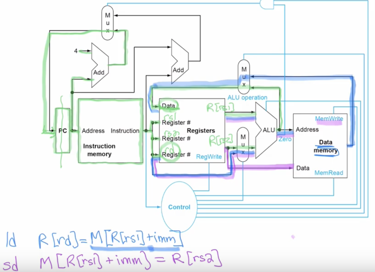
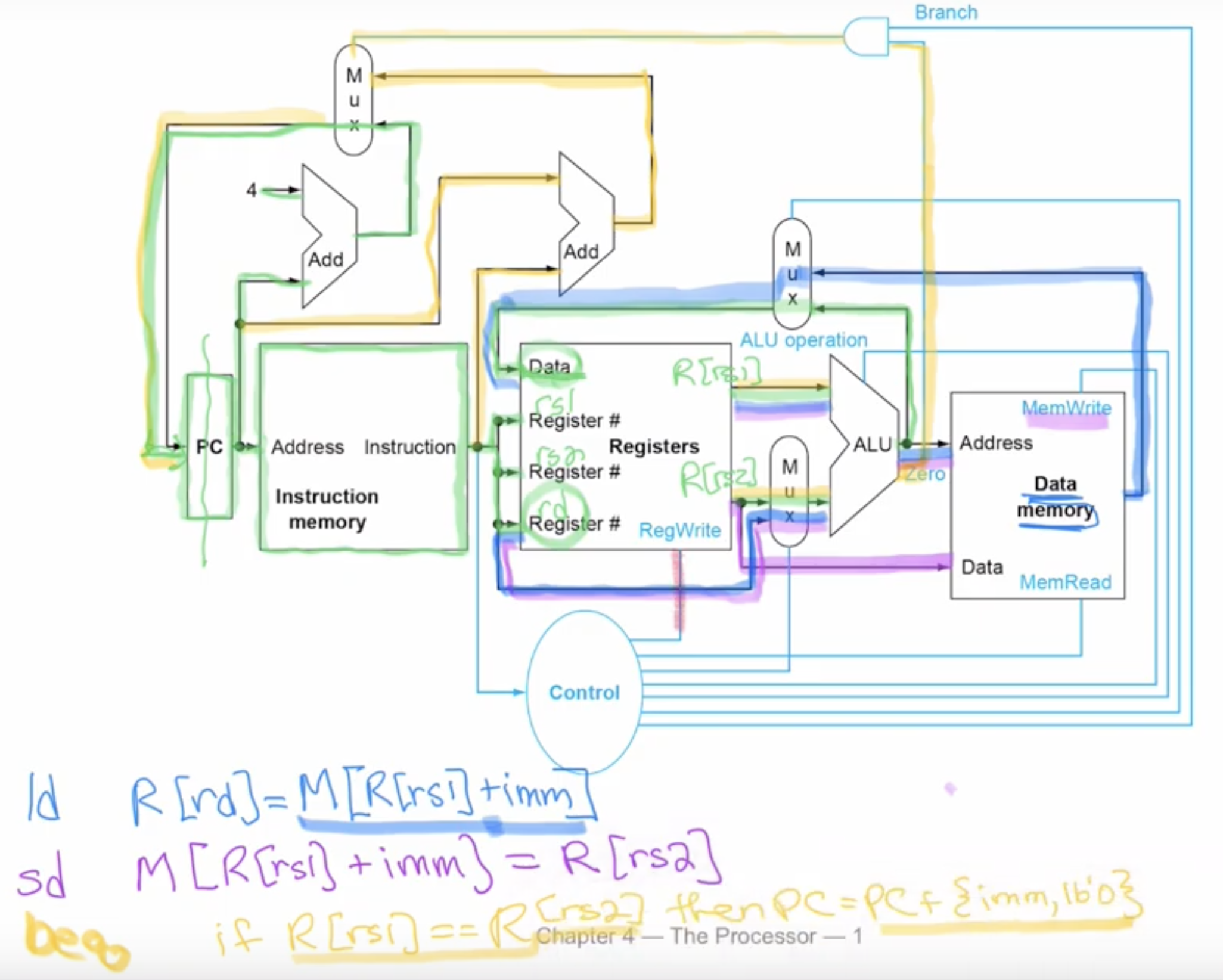
Simple Representation of the Hardware
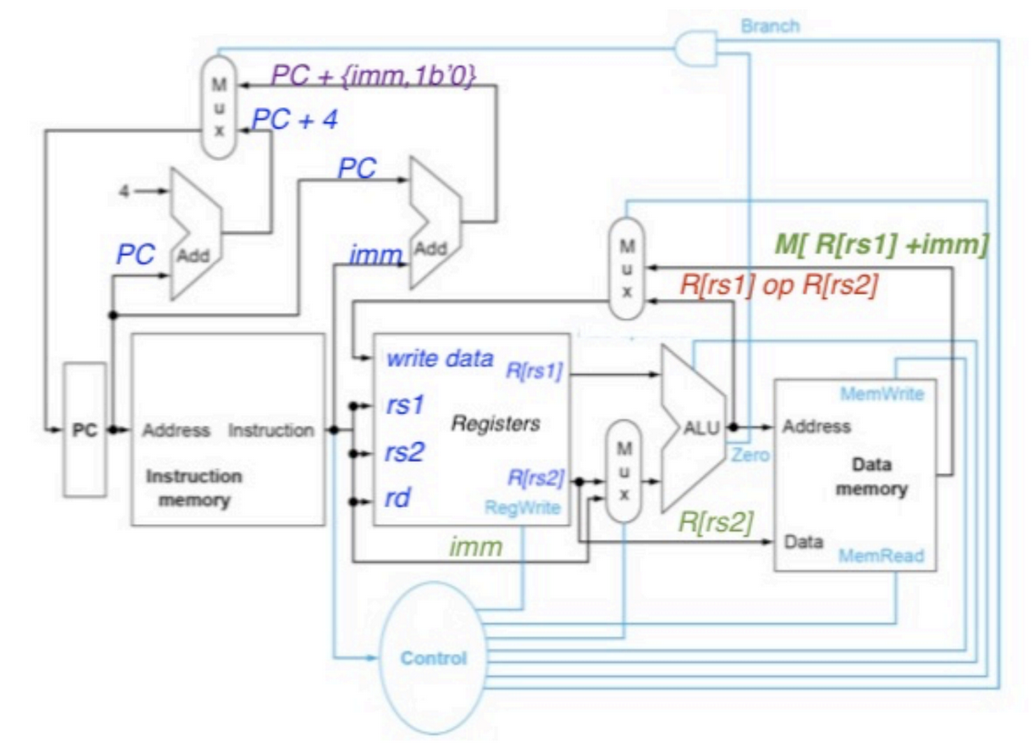
- opcodes of instructions go into the control section of combinational logic.
- determines which register is chosen or none, what are rs1, rs2 if applicable, if we should read or not to memory, if we should write or not to memory.
- PC is its own edged-triggered flip flop.
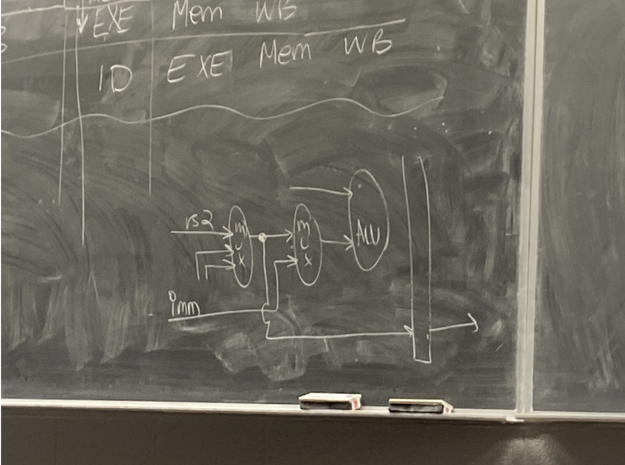
- The mux between the registers (Register file) and the ALU is for either using an immediate value or a register, based on the instruction.
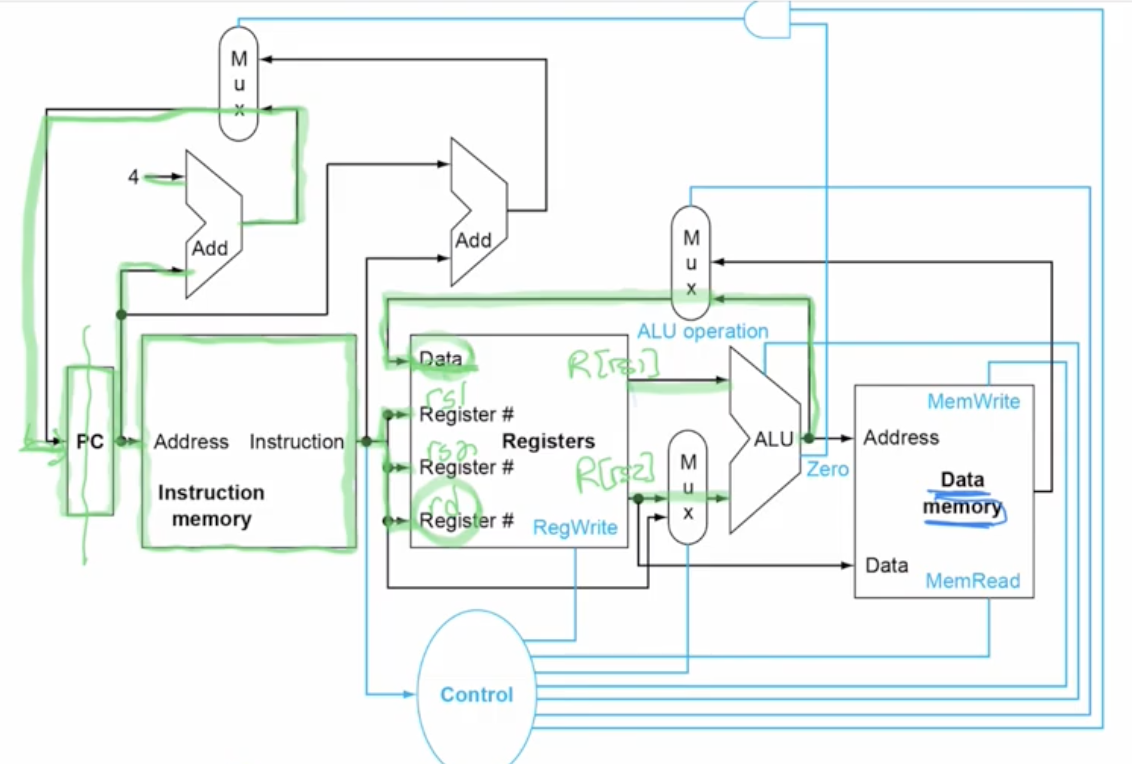
Set of instructions 1 cycle processor
Add
R-type instruction path
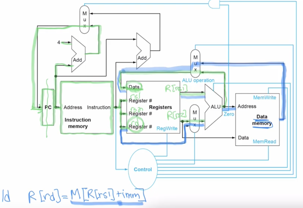
ld: R[rd]=M[R[rs1]+imm]
The immediate comes from our instruction into the second input of the MUX to go into the [ALU].
Add R[rs1] coming out of the register file into the ALU.
The output of the ALU is the address going into the data memory. With this address We can determine which data in the memory we are going to read out. M[R[s1]+imm] this data we read out, will be sent back to the register file (use the second mux).
sd: M[R[rs1]+imm] = R[rs2]
Send the data from the register to the memory. Storing in the memory. R[s1] + imm value comes into the ALU from the register file to denerate the address, instead of reading from data memory, we write the data and storing data into the data memory. R[s2] is used to send the data into the data memory, to do a MemWrite: store data instruction. Similar to ld, but we have the data coming from R[s2] into Data memory to write data instead.
beq: if R[rs1] == R[rs2] then PC = PC + {imm, lb’0}
The ALU compares R[rs1] to R[s2] (by doing substraction actually), if the result comes out to be 1, meaning they are equal, it outputs this data called 0, the signal on this wire coming will equal 1. It will control the MUX. This mux determines what loads in the PC. We want to offset it by the immediate value instead of 4. The immediate value is part of the instruction which is converted to number. Current PC is added to the immediate to jump to the label if the branch is equal to 0.
Control
Control controls the RegWrite, connected and tell us if we need to RegWrite to the destination register or not. Control the MUXs. Control the Branch. Control the MemWrite and MemRead. Also controls the ALU operation, add, sub, etc. All coming from the actual instruction, the opcode of the instructions: combined with f3 and f7 going into the Control to tell us how to interpret the instruction, to grab the different bit from the instruction to control the hardware so that we perform the actual operations.
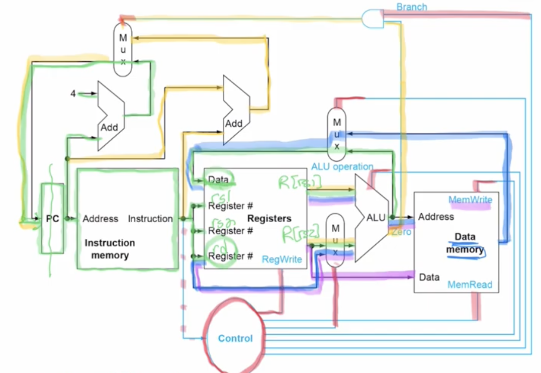
ALUOp from Control to ALU control to ALU
p.4-5 of notes, video Chpater 4 Part 4.
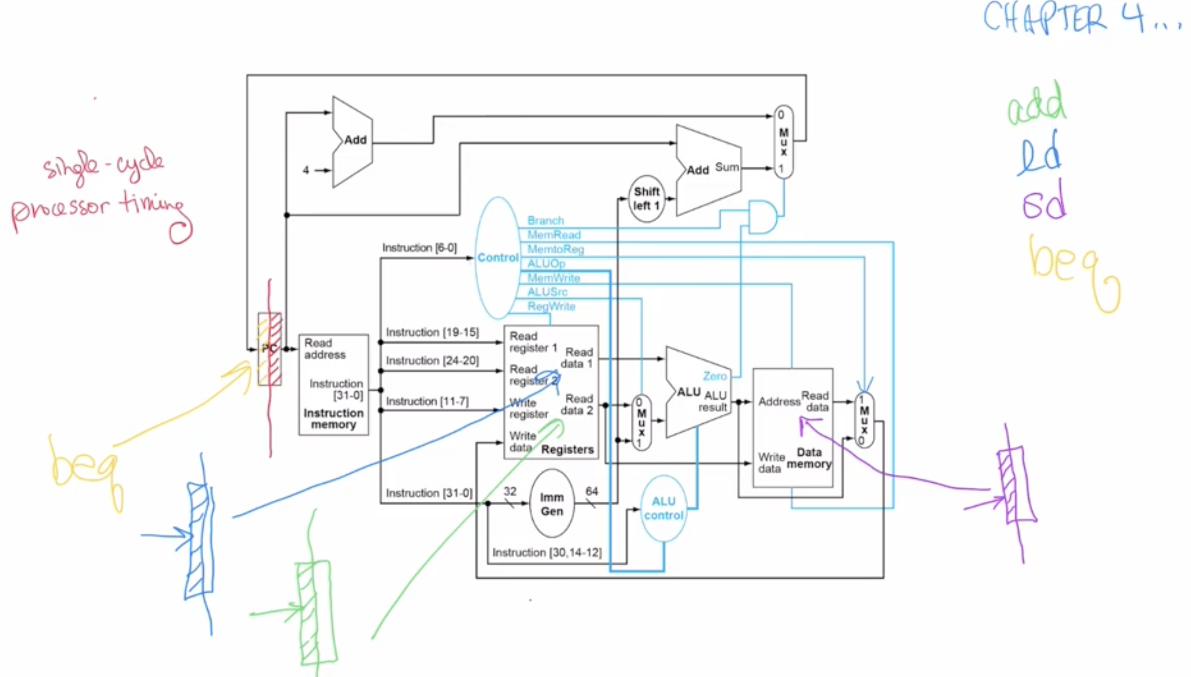
Processor Timing
Note: ld has longer delay: goes through instruction memory, register file, ALU, data memory and gets written in to the register file. Takes very long.
Add and beq are much shorter, because add only goes into instruction memory, register file, ALU and goes back gets written into the register file. Doesn’t propagate to the data memory.
Impacts single clock cycle because it limits the processor timing to the ld since it takes more time, very ineficient. Execution is slowed down by the longest delay from the critical path.
⇒ DO PIPELINING to improve the thrupe
Specify control signals (1 of {0, 1, X}) for:
-
Branch:
- 1 if branching instruction
- 0 if not branching instruciton
-
MemRead:
- 1 if we are reading from memory
- 0 if we are not reading from memory
-
MemWrite
- 1 if we are writing to memory
- 0 if we are not writing to memory
-
ALUSrc:
- 1 if we want to use an immediate value
- 0 when we want to use source register 2
-
RegWrite:
- 1 if we want to modify a register (the register to modify is specified by rd; destination register).
- 0 if we don’t want to modify a register
-
ALU operation:
- In this example, addition is 0010, subtraction is 0110
-
MemWrite and MemRead can’t both be on at the same time. It is generally undefined behaviour. Something somewhere (OS, CPU, etc) would have some exception thrown or something.
-
The reason why some instruction types such as UJ have such weird immediate values in binary (you have to put the bits in a weird order) is simply to minimize control logic in the CPU. By having many things be constant across all instruction types (such as rs1, rs2, rd, funct3, opcode, etc), we can reduce the need for logic such as muxes.
Arithmetic Logic Unit
Pipelining from hardware perspective
5-stage pipelined registers
- contains 5 pipelined registers
- The first step is using PC
- From PC until before IF/ID
- The second is called the “instruction decode”, we are getting the operands to the instructions we want.
- From the IF/ID pipeline register until before the ID/EX pipeline register.
Pipeline Hazards
- Structural Hazard
- Data Hazards
- When the pipeline must be stalled because one step must wait for another to complete.
- Ex: add instruction followed immediately by a sub instruction that uses that sum.
add x19, x0, x1
sub x2, x19, x3