ECE 358: Computer Networks
Book: Computer Networking - A Top-Down Approach, 8th Edition
Other’s notes:
- https://zandershah.github.io/notes/ece358/ece358.html
- http://gaia.cs.umass.edu/kurose_ross/online_lectures.htm
Labs:
- Due Sep 22, Oct 11, Nov 22
- Labs ECE358
Concepts
Chapter 1: Introduction
- Internet
- Protocol
- Protocol Layering
- FDM
- FTTH
- Switch
- Network Core
- Packet-Switching
- Circuit-Switching
- forwarding table
Chapter 2: The Link Layer and LANs
Chapter 3: Network Layer
Chapter 4: Transport Layer
Chapter 5: Application Layer
Lecture on Wifi
Final
I better do better in the final than the dogshit performance i pulled for the midterm. I really need to stop winging at my midterms (because I always go back home and do nothing during reading week.)
- Make sure to do ALL the tutorial questions
- Memorize literally everything
- Make anki flashcards lazy ass
Midterm
Info:
- Not difficult if you come to class and listen
- Open ended questions
- describe, give pros and cons
- problems similar to tutorials!
- be careful, say right stuff instead of just making up? Be precise. Will prob get part marks
- 4 simple questions on open ended
- 3 problems to solve
- Read the textbook - corresponding chapters
- The midterm has been re-scheduled on Oct 25,from 5-6:15pm in E7 4043, 4433/37.
- Everything we have seen till and including Oct. 8 is material for the midterm, i.e., Chap 1, Chap 2 and Chap 3: slides 1-18, 47-66.
- The midterm is closed book and lasts 70 minutes. There is no need for a calculator.
- Recall that no questions will be answered during the exam. If in doubt, write your assumptions.
- For the open-ended questions (e.g., describe Aloha), the more you say (if it is correct) the better. For the problems, we are interested in your thought process, so explain what you are doing.
Chapter 1-2
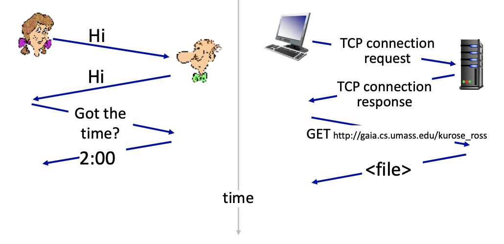
What’s a protocol?
- Defines the format, order of messages and received among network entities, and actions taken on message transmission, receipt.
A human protocol and a computer network protocol:
Protocols that you know…
- Wifi, Bluetooth, Ethernet, etc.
- USB
- Skype
Protocols that you might know…
- TCP (Transport Control Protocol)? L4
- BGP (Border Gateway Protocol) ? L3
- AKA (Authentification and key Agreement)? L3
- IPV4 and IPV6 L3
A closer look at Internet structure
- Network edge:
- hosts: clients and servers
- run application programs
- servers often in data centers
- Client/server model
- hosts: clients and servers
- client host requests, receives service from always-on server
- e.g. Web browser/server
- Peer-peer model (ECE 416)
- minimal (or no) user of dedicated servers
- e.g. Skype, BitTorrent
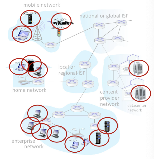
- Access networks, physical media:
- wired, wireless communication links
- Edge routers
- Ex: home network, mobile network, wifi/5g network, wireless links
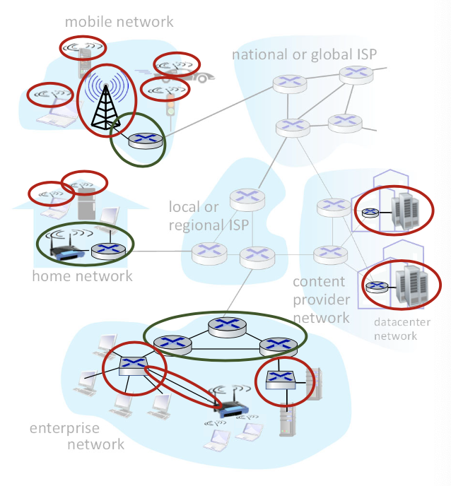
- Network core:
- interconnected routers
- the reality is less simple (and uglier): plenty of middleboxes
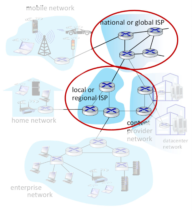
Links: digital communications
- This is not a course on digital communication, however it is important to understand the building blocks of networks. Links definitely form an important building blocks of networks!

At the lowers level, the transmitter transforms the message into a signal suitable for transmission over the physical medium. It involves energy to perturb a physical medium (perturb the voltage in a wire, create vibration in a string, perturb electromagnetic waves, etc.).
Analog vs Digital SIgnal
Analog is a signal that can be anything. Hard to reconstruct the signal. However, with digital signal, transmitter send bits (0 or 1). Much easier to decipher. (Still complex, but for the purpose of this course, we should understand that digital is better)
Transmitters can vary in prices, a pricier transmitter can do much more, something about channels.

- Encoder: to compress and add redundancy to optimize detection at the receiver.
- Modulator: to convert encoder output to a format suitable for the physical medium (modulate to the carrier frequency for radio transmission or generate light pulses for fiber)
4 basic phenomena that limit the transmission of bits by electromagnetic waves
Repeater: used to recover from attenuation Distortion: Dispersion: power is decreasing, and bandwidth becomes larger Noise:
can probably find the graphs in the textbook They make transmitting difficult!
Links: physical media
- physical link: what lies between transmitter & receiver
- guided media:
- signals propagate freely, e.g., radio
- guided media:
Three important characteristics of a transmission system
- Propagation delay
- Time required for signal to travel across media
- Example: electromagnetic waves travel through space at the speed of light (3x10^8 meters per second)
- The speed of light is medium dependent. Electromagnetic waves travel through copper or fiber at about 2/3 of this speed.
- Bandwidth/rate
- Bandwidth: Maximum times per second the signal can change (in Hertz)
- Rate: Number of bits that can be transmitted on the link in a given unit of time (i.e., C bits/s). It depends on length of the medium and the capability of the transmitter. Ex: 1 Mb/s, means that it takes the transmitter s to transmit (push out a bit)
- WE are never going to mix bandwidth and rate. Rate is in bits/sec
- Bit Error Rate (BER)
- Probability that a bit is in error, e.g., BER=10^-2 1 bit out of 100 is in error.
Twisted pair (TP)
- Inexpensive and easy to install
- two insulated copper wires
- Category 5: 100 Mbps, 1Gbps Ethernet
- Category 6: 10 Gbps Ethernet
Coaxial cable:
- two concentric copper conductors
- bidirectional
- broadbrand:
- multiple frequency channels on cable
- 100’s Mbps per channel
Fiber optic cable:
- glass fiber carrying light pulses, each pulse a bit, flexible
- high-speed operation:
- high-speed point-to-point transmission (10’s-100’s Gbps)
- low error rate:
- repeaters spaced far apart
- immune to electromagnetic noise
Wireless radio
- signal carried in various “bands” in electromagnetic spectrum
- no physical “wire”
- broadcast, “half-duplex” (sender to receiver) a communication system that allows data transmission in both directions but not at the same time
- propagation environment effects:
- reflection
- obstruction by objects
- Interference/noise
Access networks and physical media
Q: How to connect end systems to edge router?
Residential access networks: digital subscriber line (DSL)
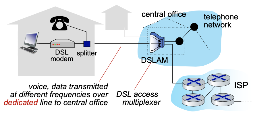
- use existing telephone line to central office DSLAM
- data over DSL phone line goes to internet
- voice over DSL phone line goes to telephone net
- 24-52 Mbps dedicated downstream transmission
- 3.5-16 Mbps dedicated upstream transmission
- FDM: frequency division multiplexing is the technique of combining different frequency signals over a common medium and transmitting them simultaneously
Residential access networks: cable-based access
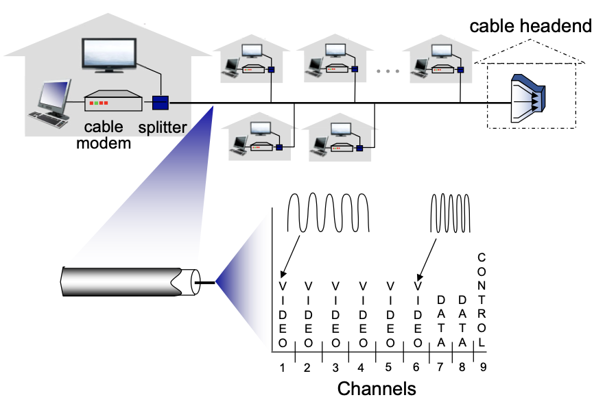
FDM:
Residential access networks: fiber at home
- Optical links from central office to the home
- Two competing optical technologies:
- Passive Optical network (PON)
- Active Optical Network (AON): switched Ethernet
- Much higher Internet rates; fiber also carries television and phone services
Residential access networks: home networks
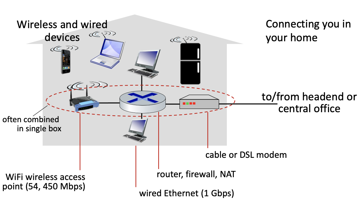
Access networks: enterprise networks
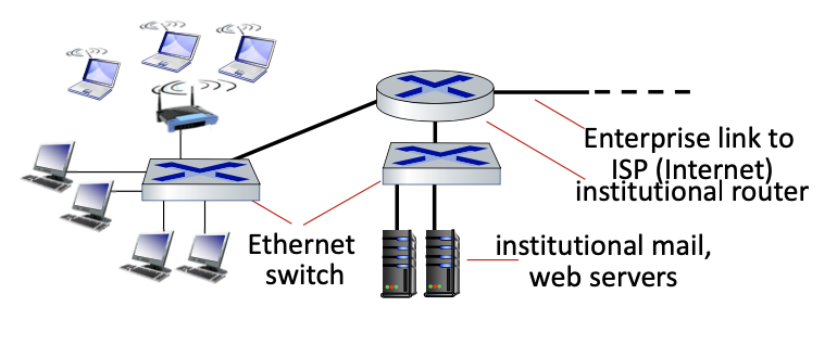
- companies, universities, etc.
- mix of wired, wireless link technologies, connecting a mix of switches and routers (we’ll cover differences shortly)
- Ethernet: wired access at 100 Mbps, 1Gbps, 10Gbps
- Wifi: wireless access points at 11, 54, 450 Mbps
Access networks: data center networks
- high-bandwidth links (10s to 100s Gbps) connect hundreds to thousands of servers together, and to Internet
Slide 25 of Lecture2+
Switching: Motivation
- We want 6 users to be able to communicate with any other user. How many links?
- Three ways:
- a. Fully meshed
- b. Every node is connected to a central switch and
- c. Hierarchical network with inter-switch links which are shared
- For b. and c. information flow will traverse more than one link and switch is required at junction of two or more links.
- Switch is a device that enables the forwarding of information from any input link to any output link
- Imagine the problem if we have one billion users…
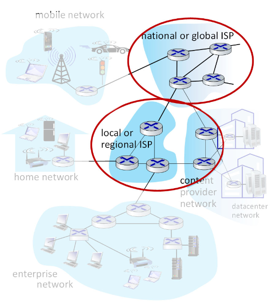
The network core
- mesh of interconnected routers
- packet-switching: hosts break application-layer messages into packets
- network forwards packets from one router to the next, across links on path from source to destination
- A packet from your computer to a server might cross many many routers (and links)
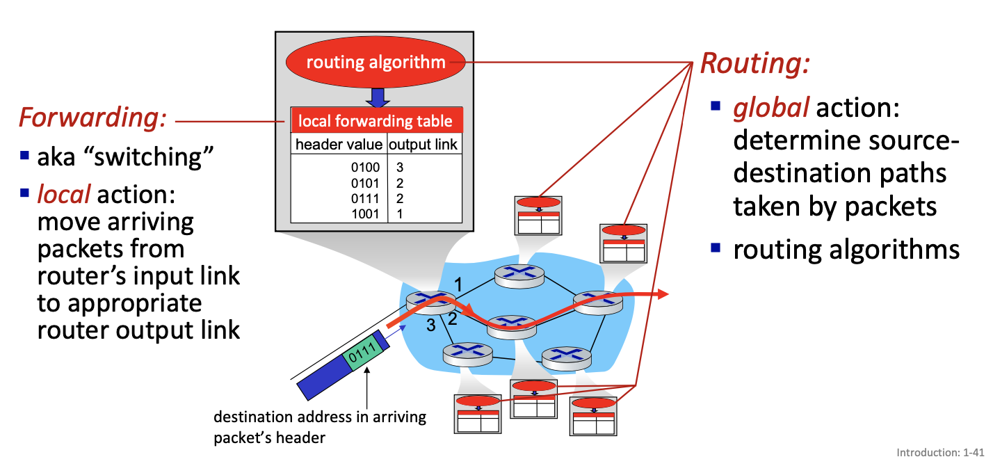
Two key network-core functions
Packet-switching: at the source
host sending function:
- takes application message
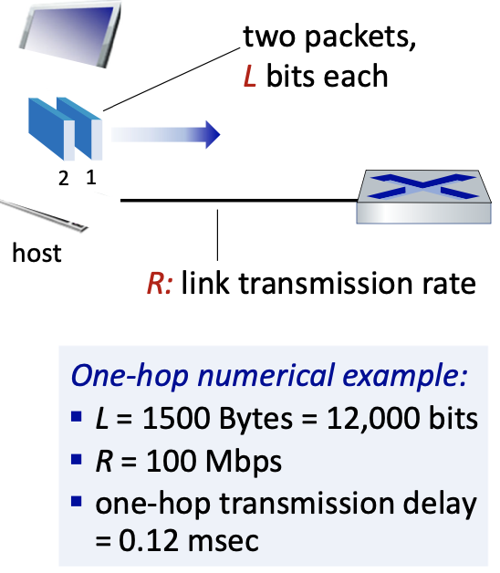
- breaks into smaller chunks, known as packets, of length L bits
- transmits packet into access network at transmission rate R
- link transmission rate, aka link capacity
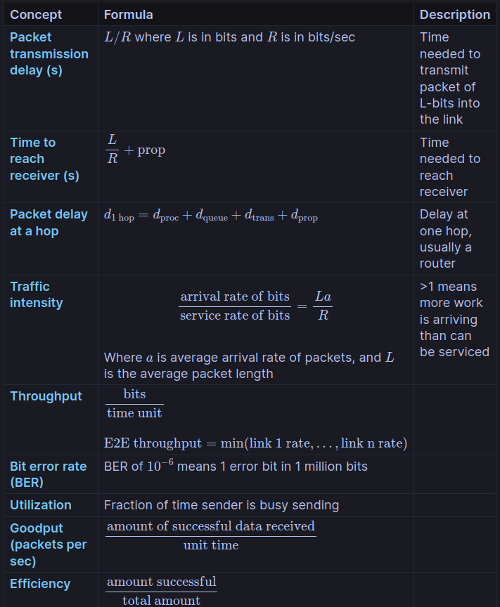
packet transmission delay = time needed to transmit L-bit packet into link = bits/(bits/sec)
Packet transmission (on each link)

- packet transmission delay: takes L/R seconds to transmit (push out) L-bit packet into link at R bps
- Takes L/R+prop seconds (prop=propagation delay) for the packet to fully arrive at the receiver
Store and forward: entire packet must arrive at router before it can be transmitted on next link
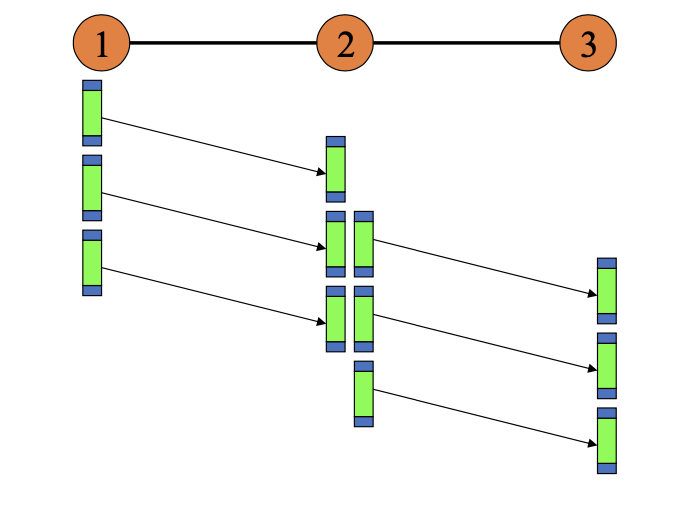
(insert picture that explains it)
Substitute: didn’t listen
Tuesday Sep 17
Started from slide 34 of Lecture2+
Alternative to packet switching: circuit switching
Is packet switching always better? No
If you have money, change it to circuit switching. Good for high ping applications.
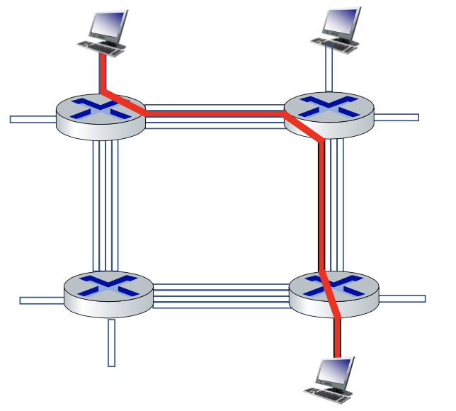
In circuit switching, network resources (e.g., bandwidth or time) are statistically divided into small pieces called circuits (once and for all).
end-to-end resources allocated to, reserved for “flow” between source and destination
- in a diagram, each links has four circuits.
- call gets 2nd circuit in top link and 1st circuit in right link.
- dedicated resources: no sharing (at the circuit level, sharing of the link though)
- circuit segment idle if not used by call
- call setup required
- commonly used in traditional telephone networks
Packet switching vs. Circuit switching
Packet switching versus circuit switching
Example:
- 1Gb/s link
- each user:
- 100 Mb/s when “active”
- active 10% of time
Q: how many users can use this network under circuit-switching and packet switching?
- circuit-switching: 10 users
- packet switching: with 35 users, probability > 10 active at same time is less than .0004
Is packet switching a “slam dunk winner”?
- a great for “bursty” data - sometimes has data to send, but at other times not
- resource sharing
- simpler, no call setup
- excessive congestion possible: packet delay and loss due to buffer overflow
- protocols needed for reliable data transfer, congestion control
- Q: How to provide circuit-like behaviour with packet switching?
- ”It’s complicated.”
Internet structure: a “network of networks”
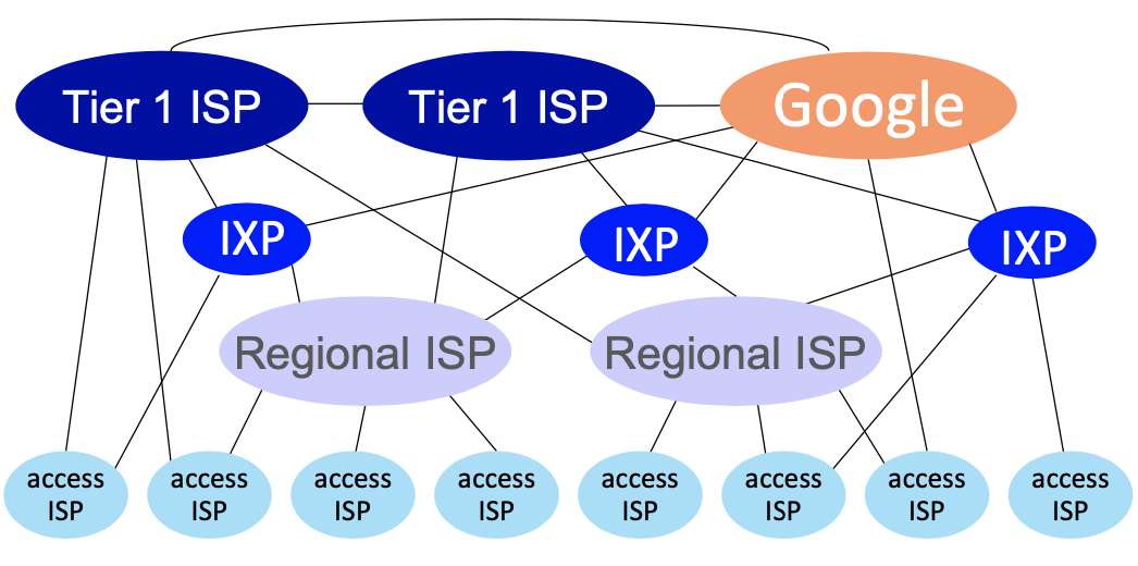
At “center”: small number of well-connected large networks
- ”tier-1” commercial ISPs (e.g., Level 3, Sprint, AT&T, NTT), national & international coverage
- content provider networks (e.g., Google, Facebook): private network that connects their data centers to Internet, often bypassing tier-1, regionals ISPs.
What goes Wrong in Data Network?
- Bit-level errors (electrical interference)
- Packet losses
- Link and node failures
- Packets are delayed
- Packets are delivered out-of-order
- Third parties eavesdrop
What is Quality of Service (QoS)
- Users must be able to rely on their network for critical tasks
- Each user might privilege some QoS metric such as:
- Packet loss
- Delay
- Delay variation
- Rates
- Prices
- Ease of installation and maintenance
- Availability/reliability
- QoS differentiation
- Privacy
- Security
QoS is dependent on type of service
- Not all services/users want everything
- Real-time services are concerned by delay and delay variation and not so much by loss
- Packet loss is a big issues for many data services
- Availability is key for strategic applications
- High capacity is a must for some video application
- Fairness is becoming a big issue for e-commerce
- Not everyone values security and privacy the same way
The Internet today is based on a "best-effort" paradigm
The network standpoint
- QoS is expensive to support. Are users really ready to pay for it?
- Does not know what to promise: i.e., no clear consensus on QoS:
- Hard guarantee?
- Differentiation?
- Guarantee implies reservation, implies some form of admission, implies a costly traffic management infrastructure: importance to aim right!
- How to price QoS?
- How to monitor QoS? Especially if based on differentiation?
- How to enforce what has been negotiated?
- How to remain scalable?
How do packet delay and loss occur?
- packets queue in router buffers, waiting for turn for transmission
- packet loss occurs when buffer
Slide 72/100 Lab 1: Taking a buffer, one server which has a rate R bit/s We have packets arriving in a random way. Q at the output of the buffer. There is a average packet arrival rate. Length of packet is also variable. Assume that all packet of the same size for simplicity in this lab.
We have 3 parameters.
: arrival rate of bits/service rate of bits If it’s less than 1, we are good.
When we do simulation, this curve:
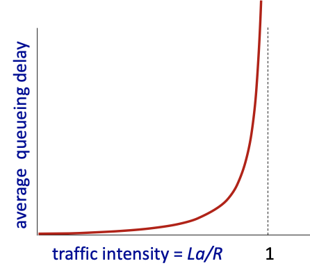
traffic intensity shouldn’t be 1! or close to 1.
We want 60% of the rate, so the delay is acceptable
Goal of the lab: Make us understand how delay varies in terms of the traffic intensity!!
Throughput
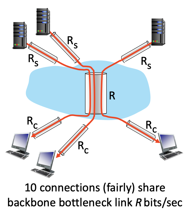
- Access is the bottleneck but often on your side
Protocol “layers” and reference models
Networks are complex with many “pieces”
- hosts
- routers
- links of various media
- applications
- protocols
- hardware, software
Question: is there any hope of organizing structure of network?
- and / or our discussion of networks?
We should know the 5 layers of reference model
- application: supporting network applications
- transport: process-process data transfer
- network: routing of datagrams from source to destination
- link: data transfer between neighbouring
- physical: bits “on the wire”
Physical and link: typically done in hardware, firmware.
Protocol is at a given layer. We have 5 layers.
Started from slide 83/100
TCP offers a connection oriented service. protect internet, no error
Packet = datagram (terminology for internet)
Link layer and physical layer: hop by hop
Slide 93/100 is what we are going to in Lab3.
Started second lecture slide

Problem with Framing. Error in the flag. Receiver would not detect the proper bit (flag), and it can loose a frame. A link can loose a packet.
- Special bit patterns:
- flag - 01111110
- idle - 01111110
Bit stuffing: whenever you see 5 consecutive 0, you insert a 0. We also do bit stuffing on the header and footer
Errors: How to deal with them?
- Noise and interference cause errors: how do we detect these? Errors are NOT independent, they come in burst.
Error detection
- Error detection is performed at Layer 2, Layer 3 and Layer 4. Done in hardware in L2 and in software in other layers
- ED: error detection bits (e.g., redundancy)
- D: data protected by error checking, may include header fields
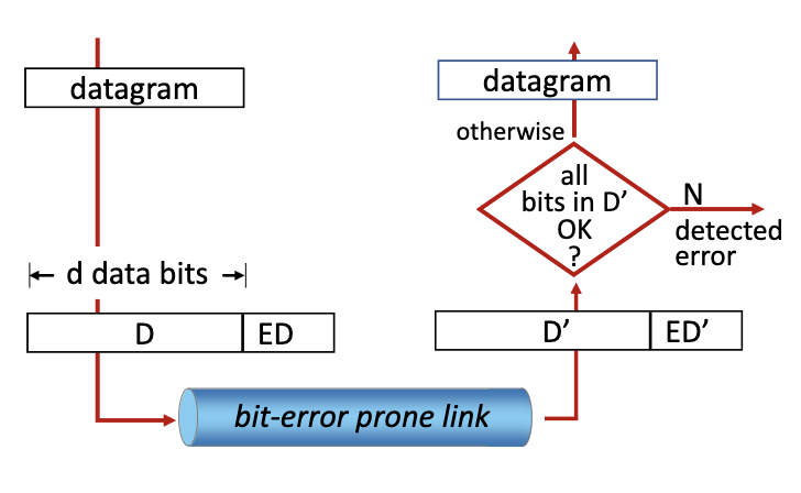
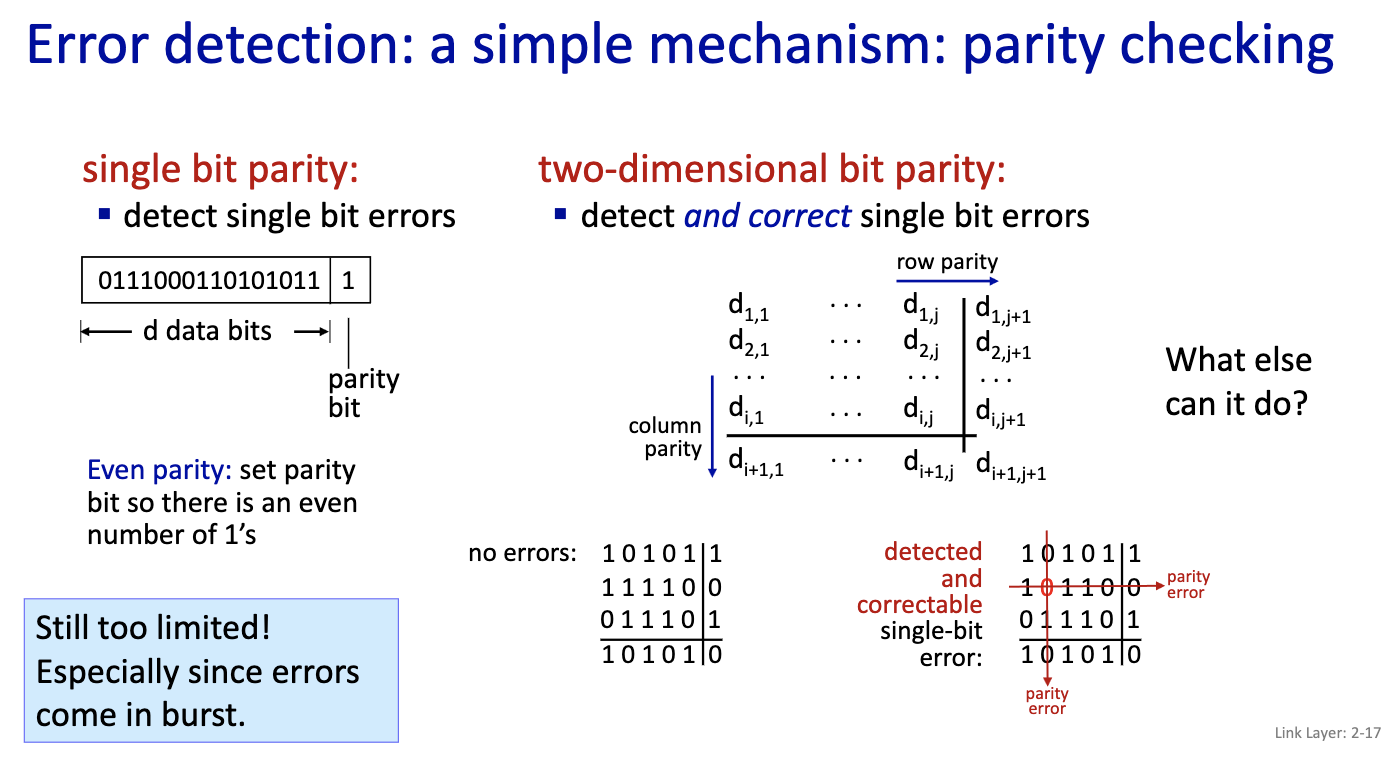
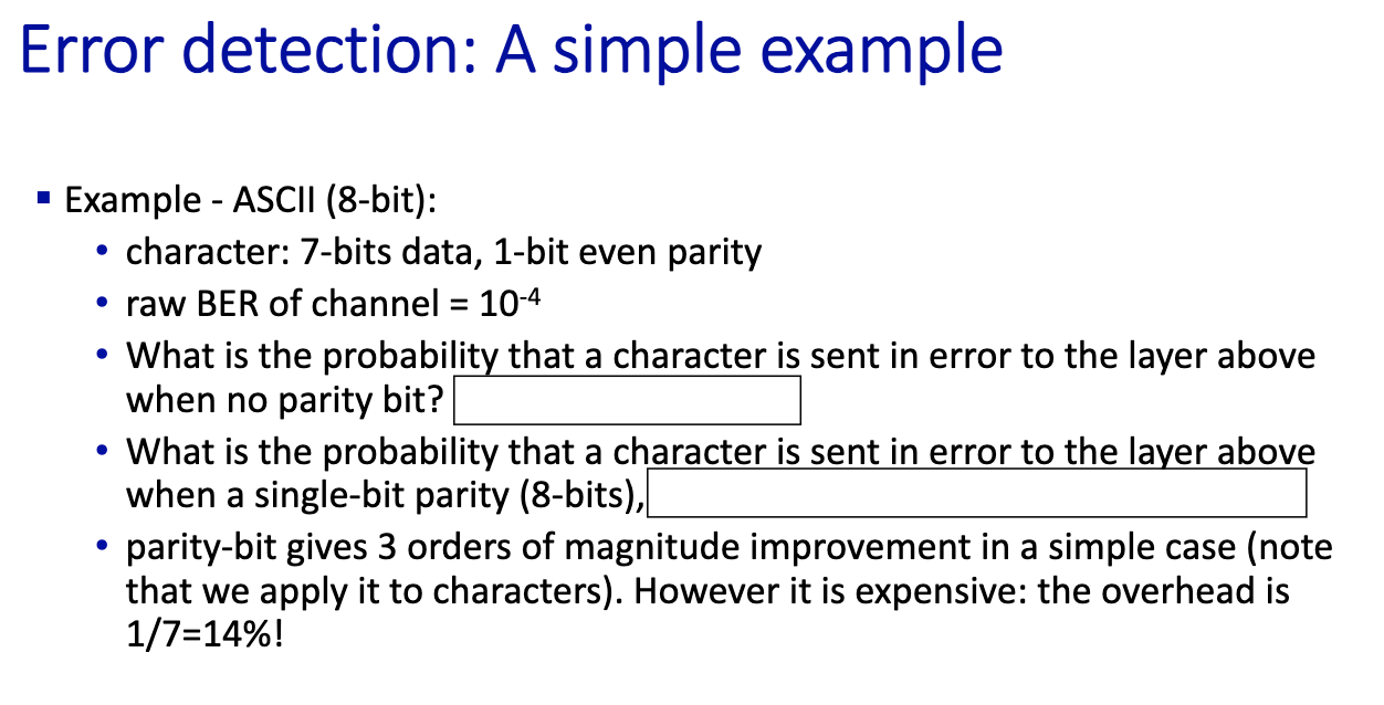
- Bit Error Rate (BER) = p is given to you
- What is the probability that a character is sent in error to the layer above when no parity bit?
- with no parity bit. so we have 7 bit
- Probability of an error 1 - P_success =
- P_success:
- That is 1-(1-BER)^7 =
- Now, we add the parity bit
- What is the probability that acharacter is sent in error to the layer above when a single-bit parity (8bits):
- I assume a p.b. detects single errors
- Probability of a success:
Cyclic Redundancy Check (CRC)
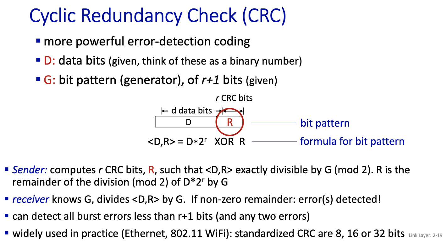
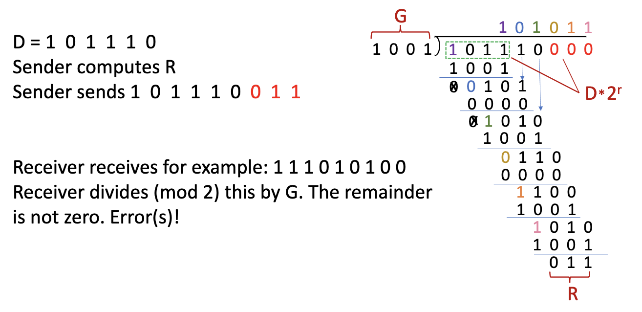
Example:
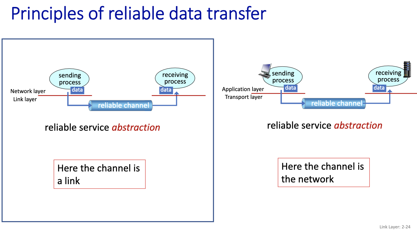
- Is it safer to do retransfer on the network or on the link?
- Unreliable network:
- Put packets out of order
- So we use a link instead
- Unreliable network:
Everything is communicated through this reliable channel. So the sender and receiver are blind from each other. Very complex problem.
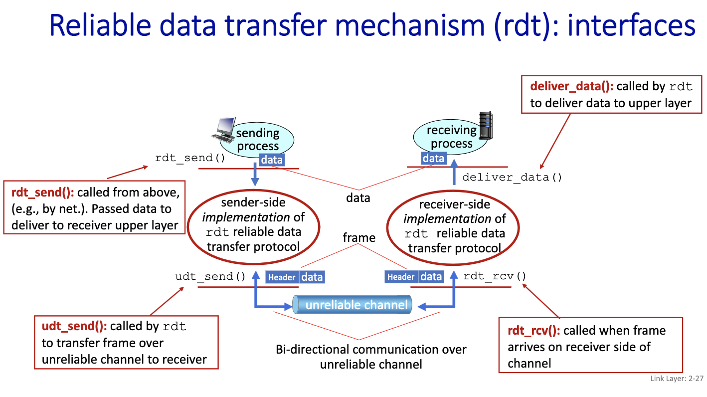
We will first look at udt_send() in detail in the next class.
What is standardized is the header and footer.
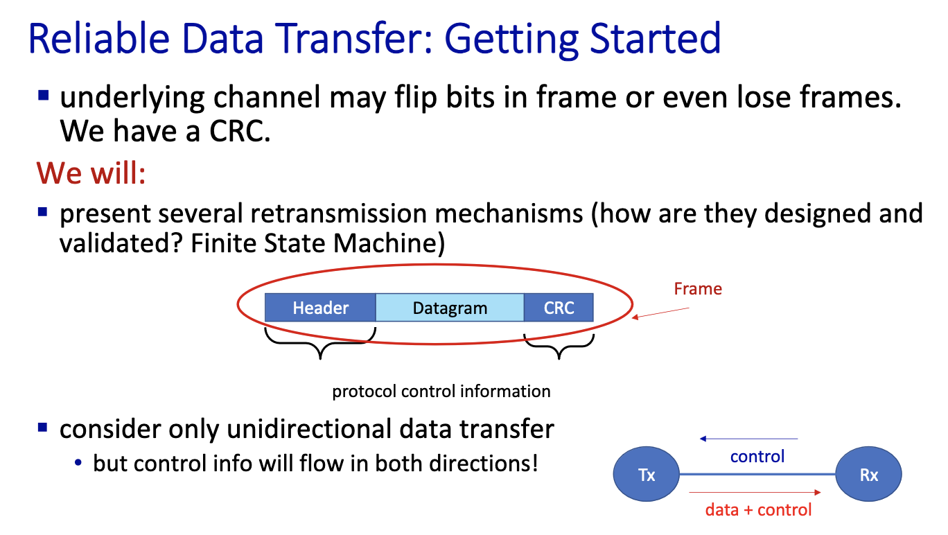
- Control information: to say that we’ve received or not. This is part of the header.
Lecture 8
Sep 26
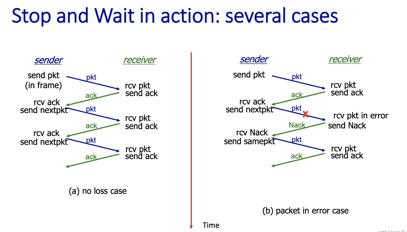
Here we didn’t consider packet loss.
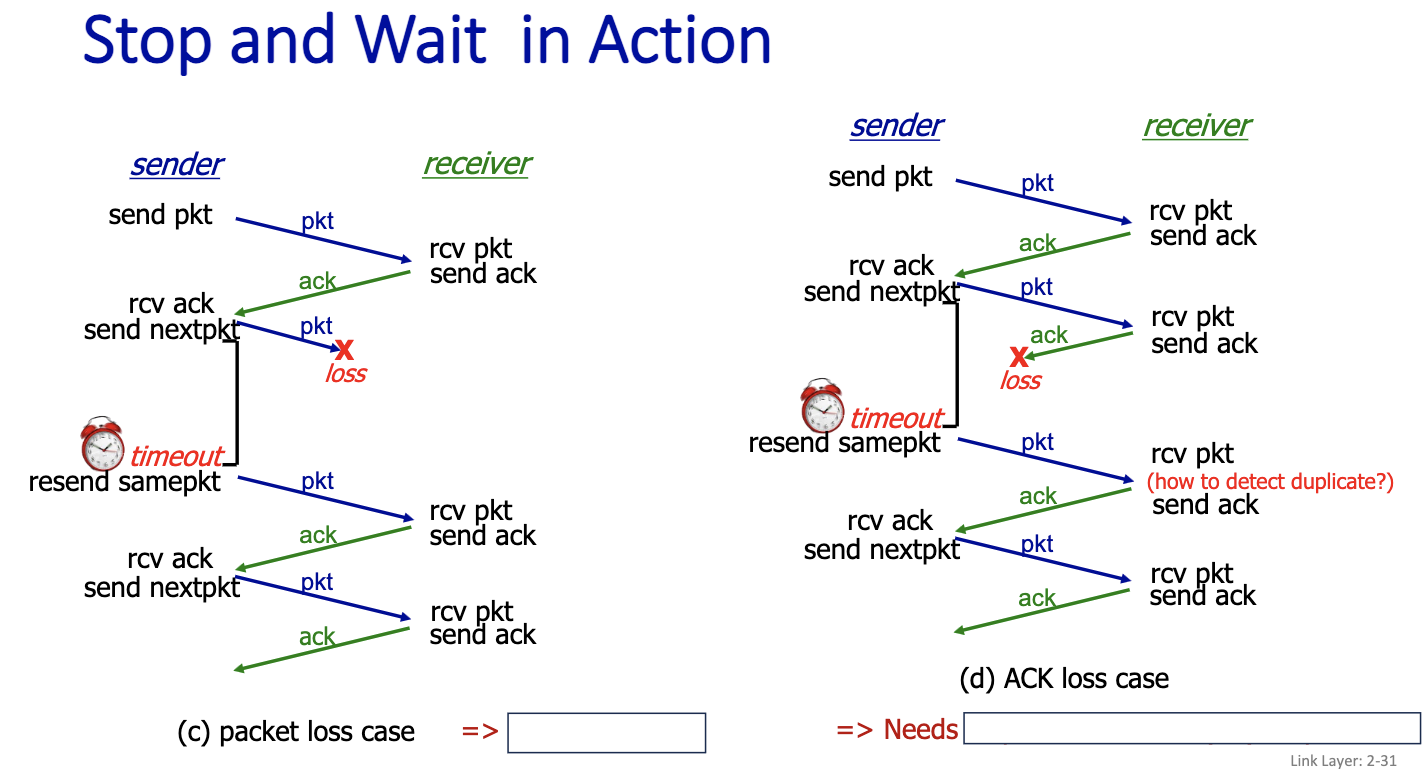
c) packet loss case ⇒ Needs timeout d) ACK loss case ⇒ Needs sequence numbers (5N) on packets.
For Stop and Wait, we only need one bit for the data sequence number!
The protocol still doesn’t work…
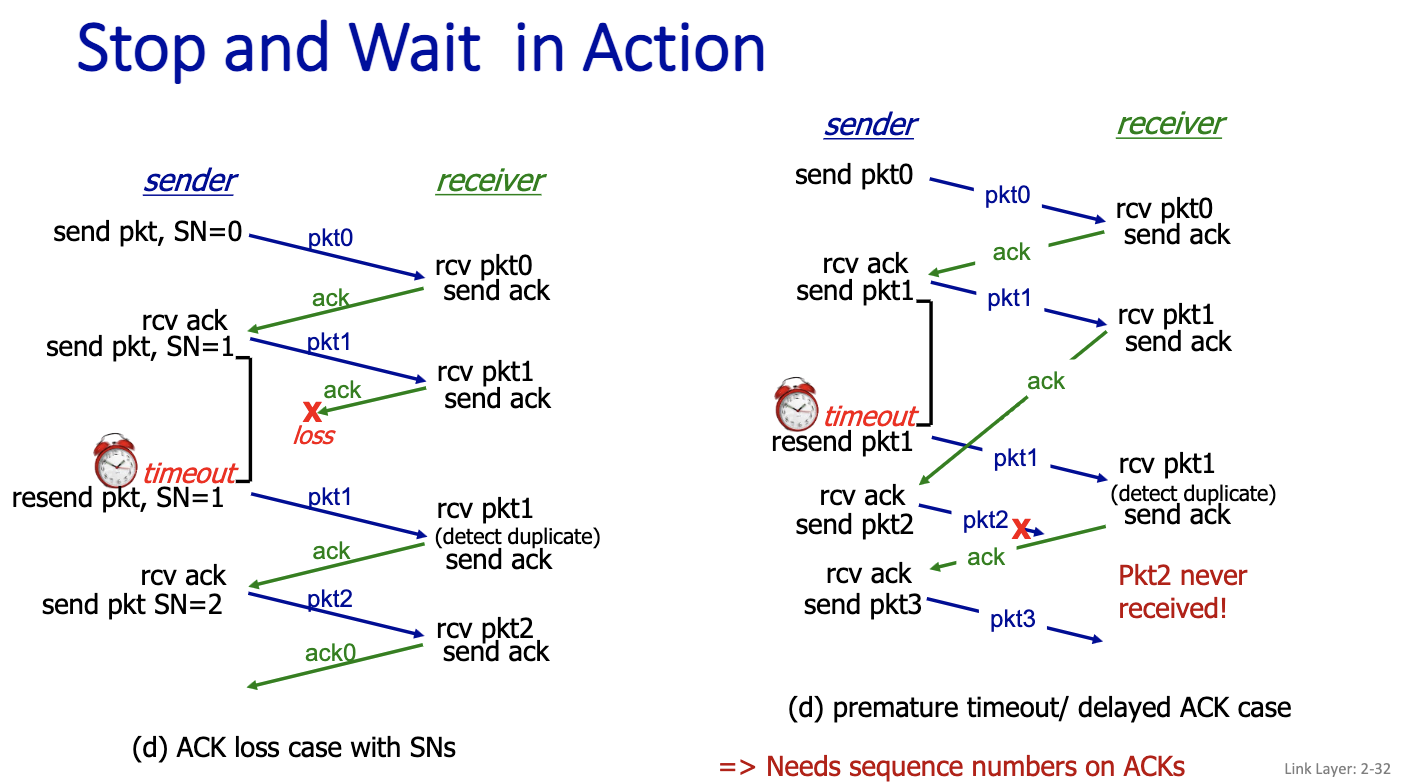
ACK is acknowledgement
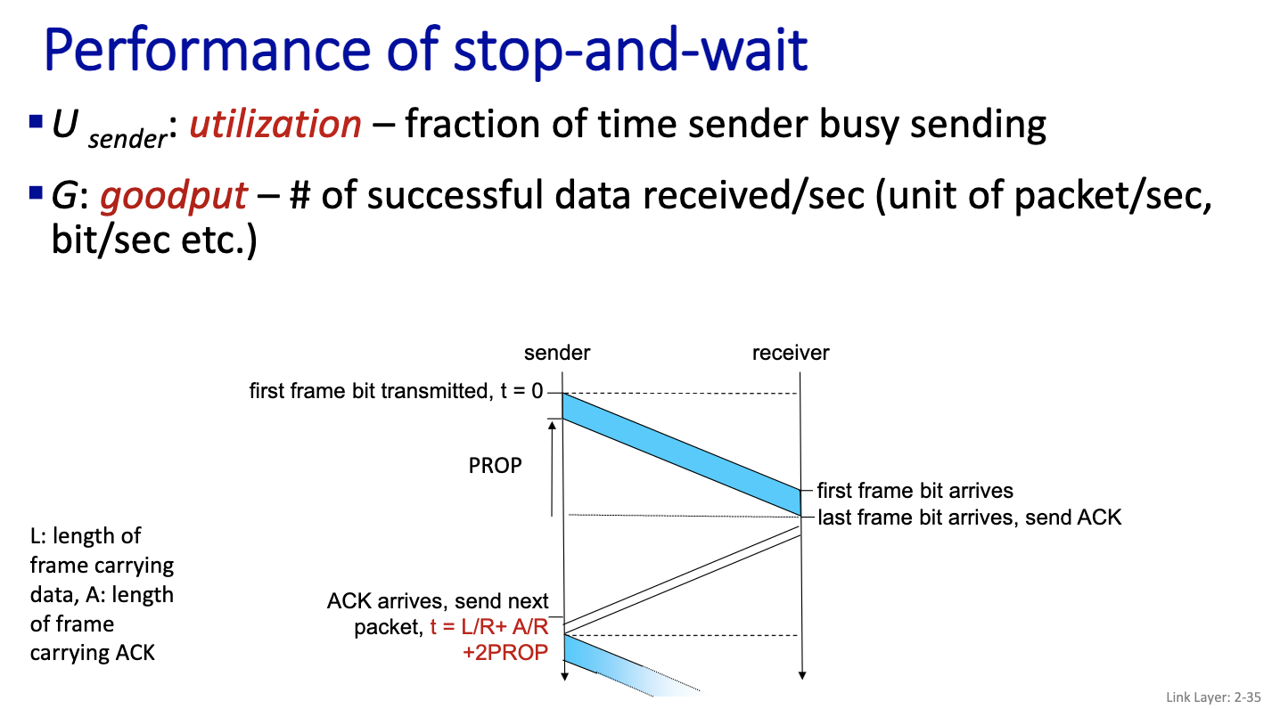
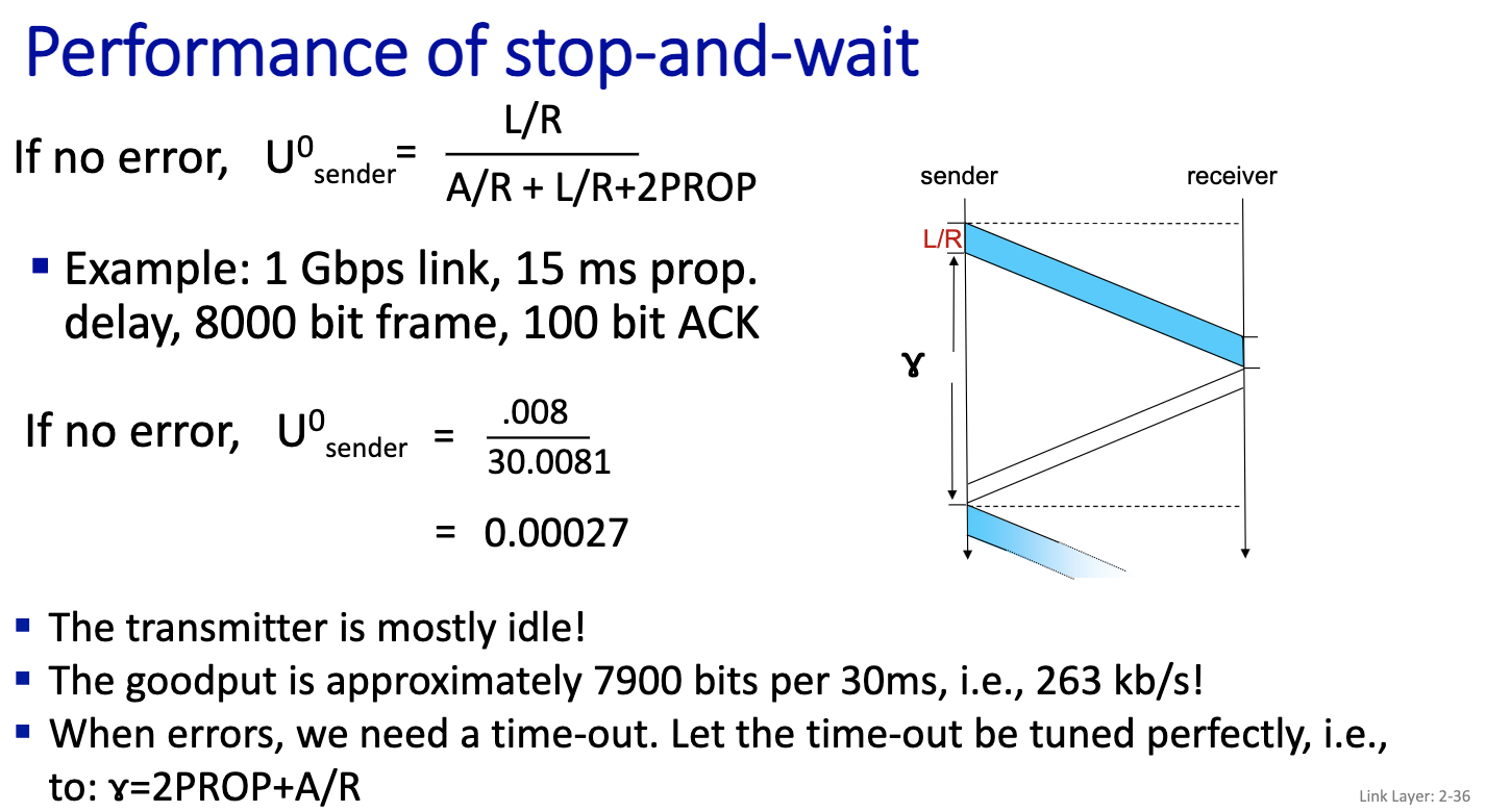
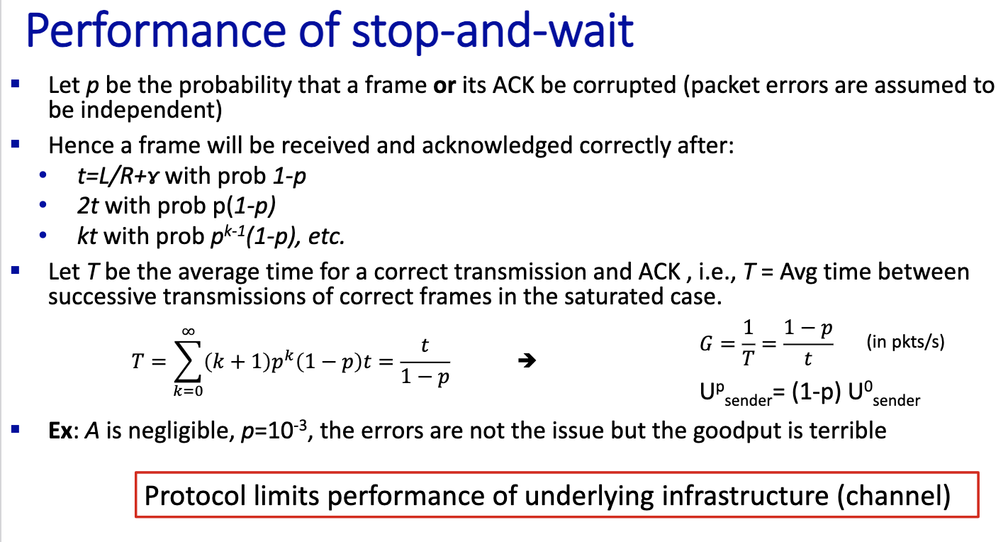
Prof did calculations in notes
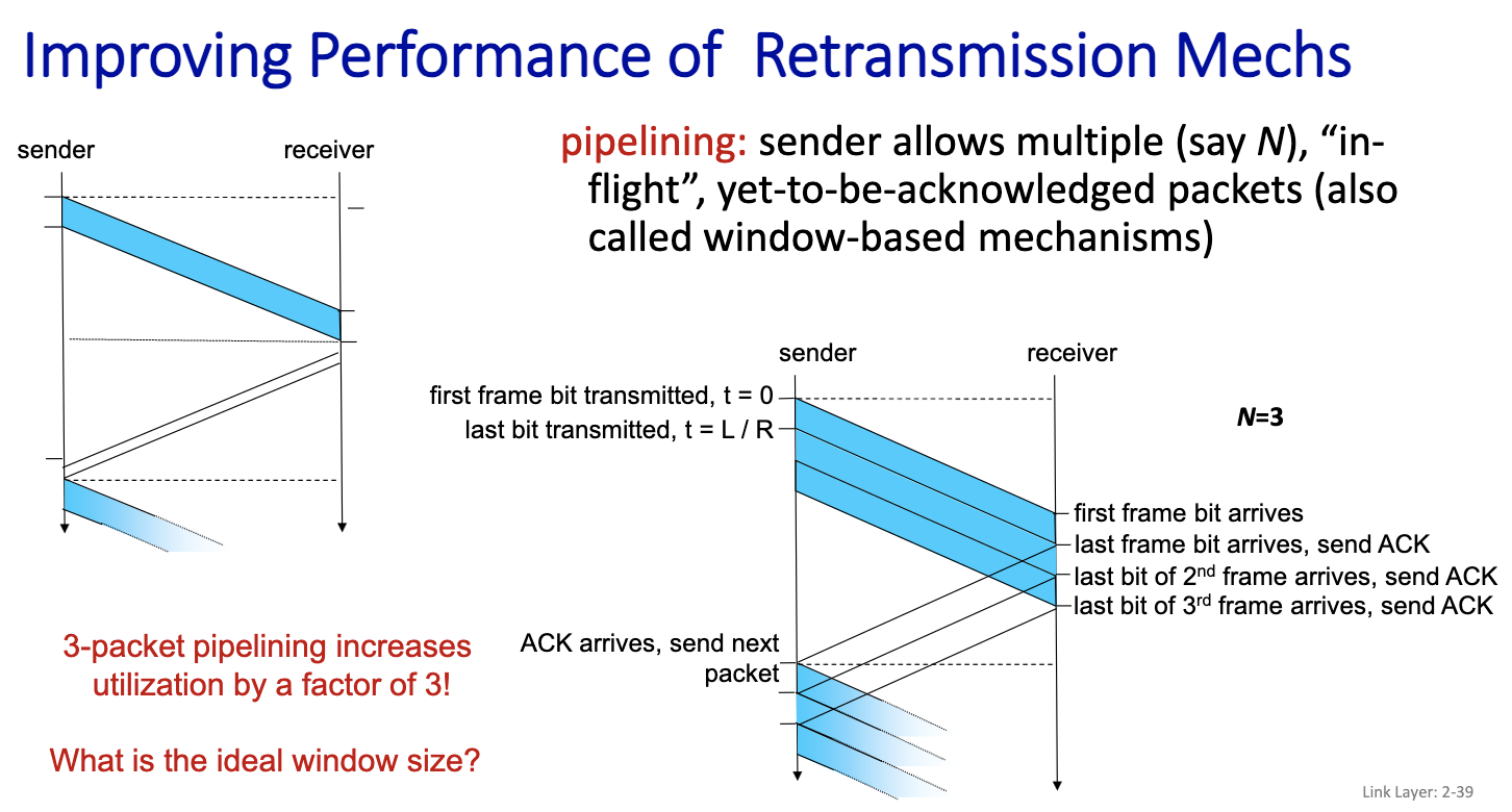
L/R + gamma is the time to send one frame = t n L/R = gamma n = floor(gamma / (L/R)) + 1
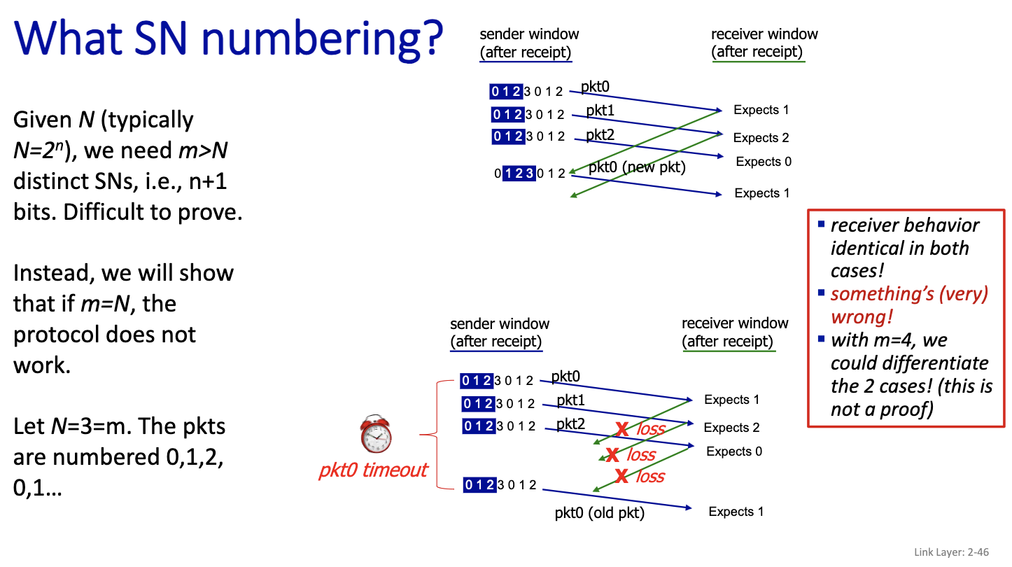
This is going to be on the exam: SN numbering
If we have a go back 4, we need 5 SN?
Notices, that packet 3 is numbered 0, because if N=3, we number the packet 0,1,2. Since only 3 sequence number. The packet 0 here contains a new packet. But for the receiver, it’s the same, it cannot make the difference between the first scenario and the second scenario in the picture. So N=m doesn’t work.
CSMA/CD
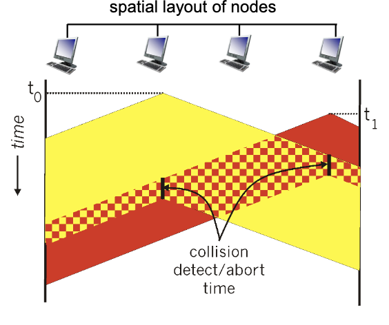
- Understanding this drawing.
- minimum frame size: make sure everyone receives the signal before the frame ends
- detects collision, sends jam signal and then abort
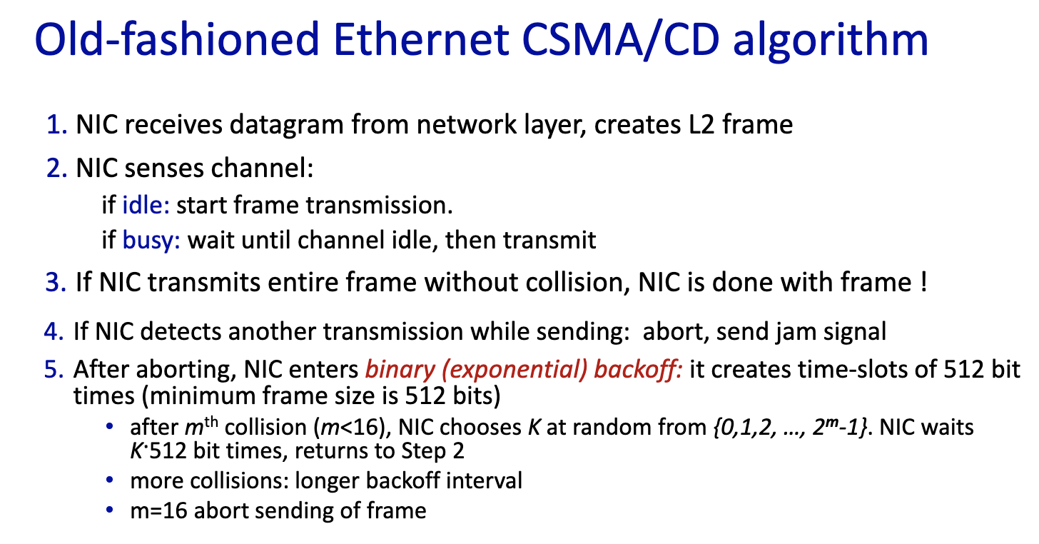
- No longer used, hence old-fashioned ethernet algorithm
- If it’s 1st collision, we choose 2 slots (same probability)
- If it’s 2nd collision, we choose 3 slots (probability 1/3)
- If it’s 3rd collision, we choose 4 slots (1/4) and so on
Don’t need to know the efficiency formula.
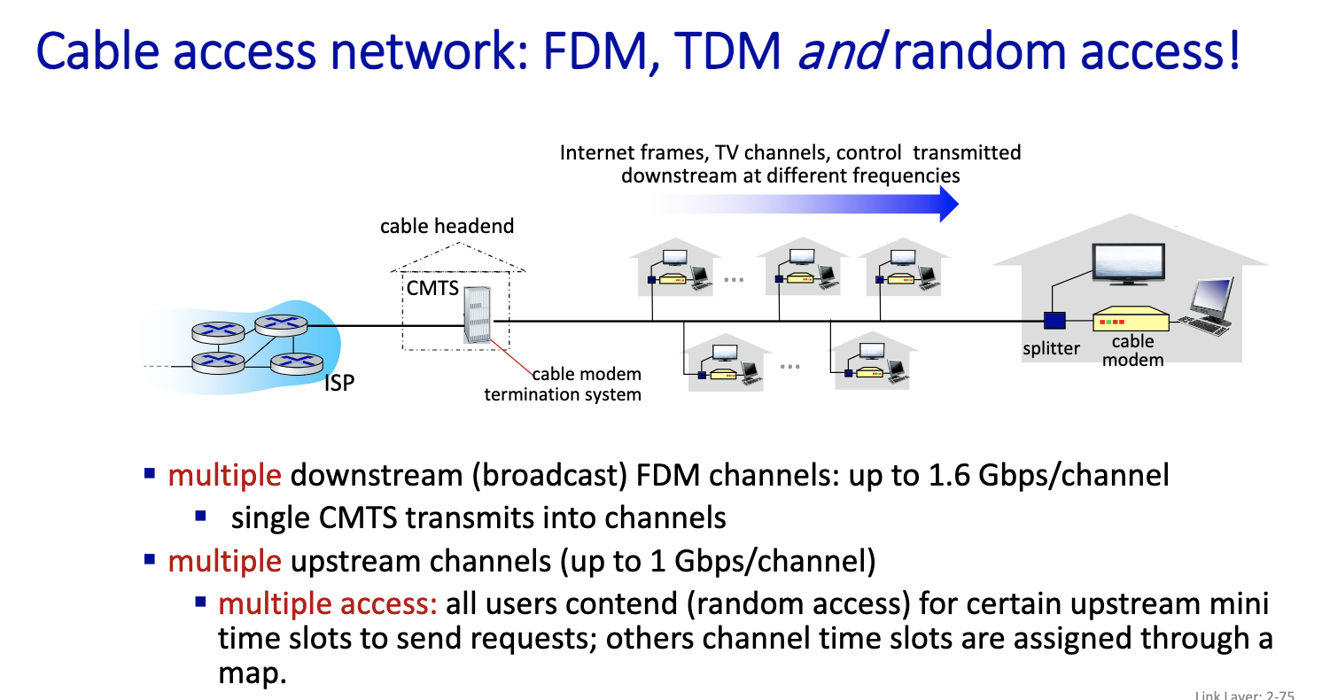
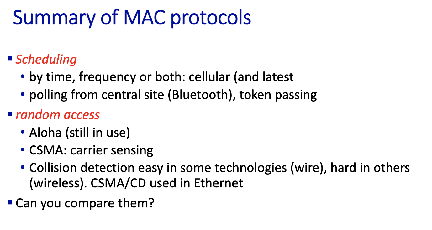
- polling used in bluetooth
- ALOHA, CSMA/CD used in Ethernet, but later we’ll see that it is not
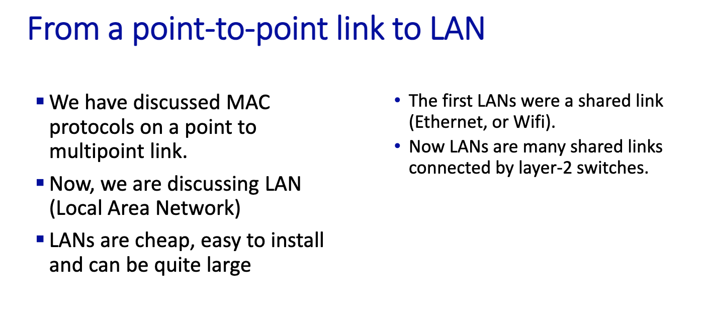
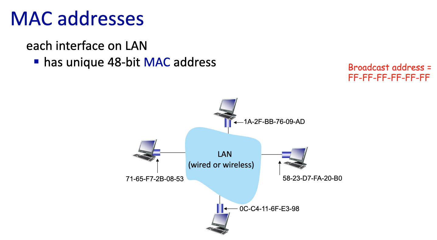
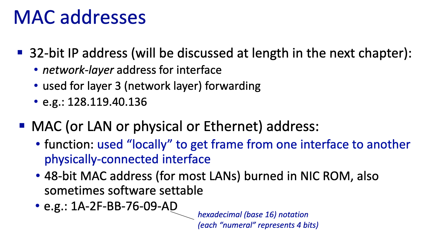
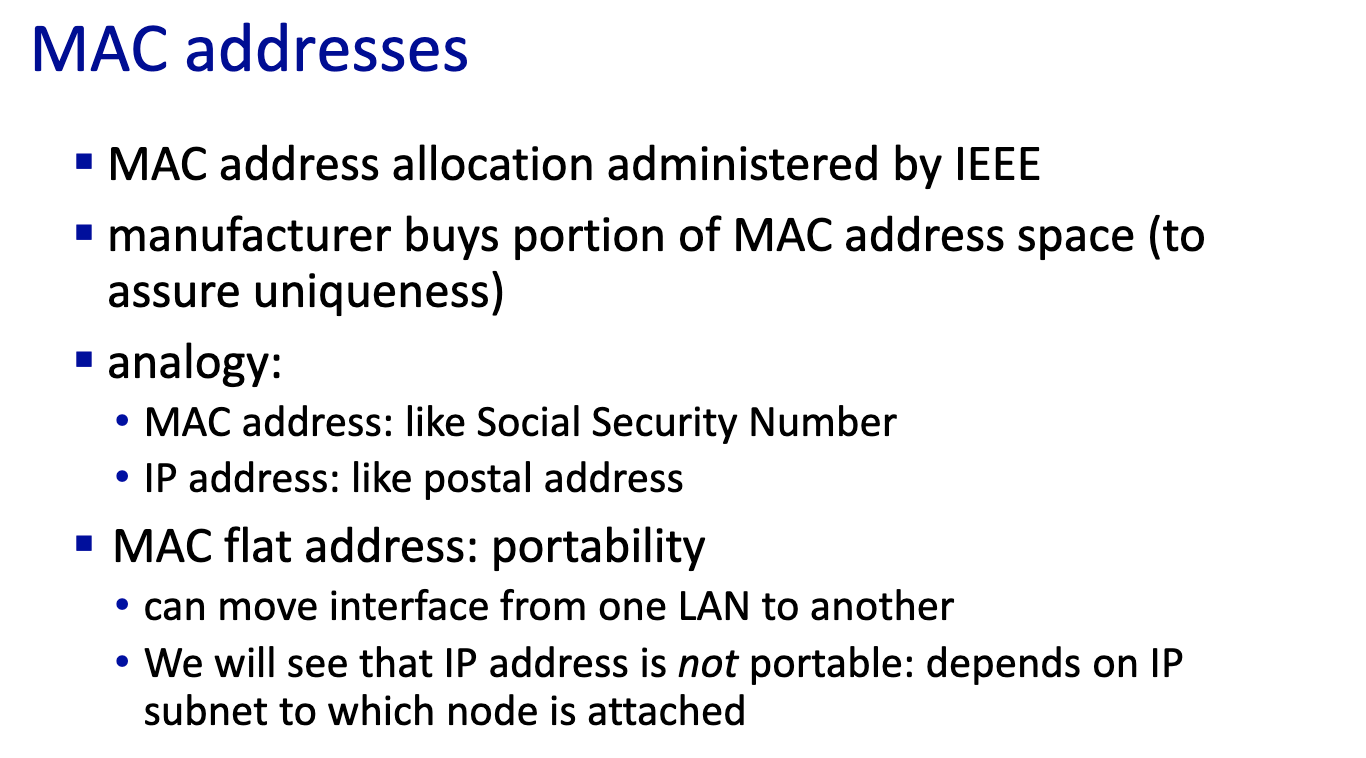
- MAC doesn’t change, comes with device
- IP address can change
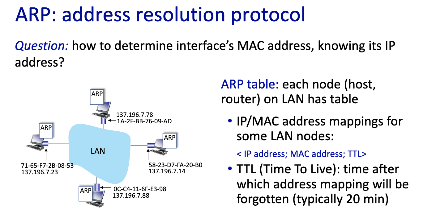
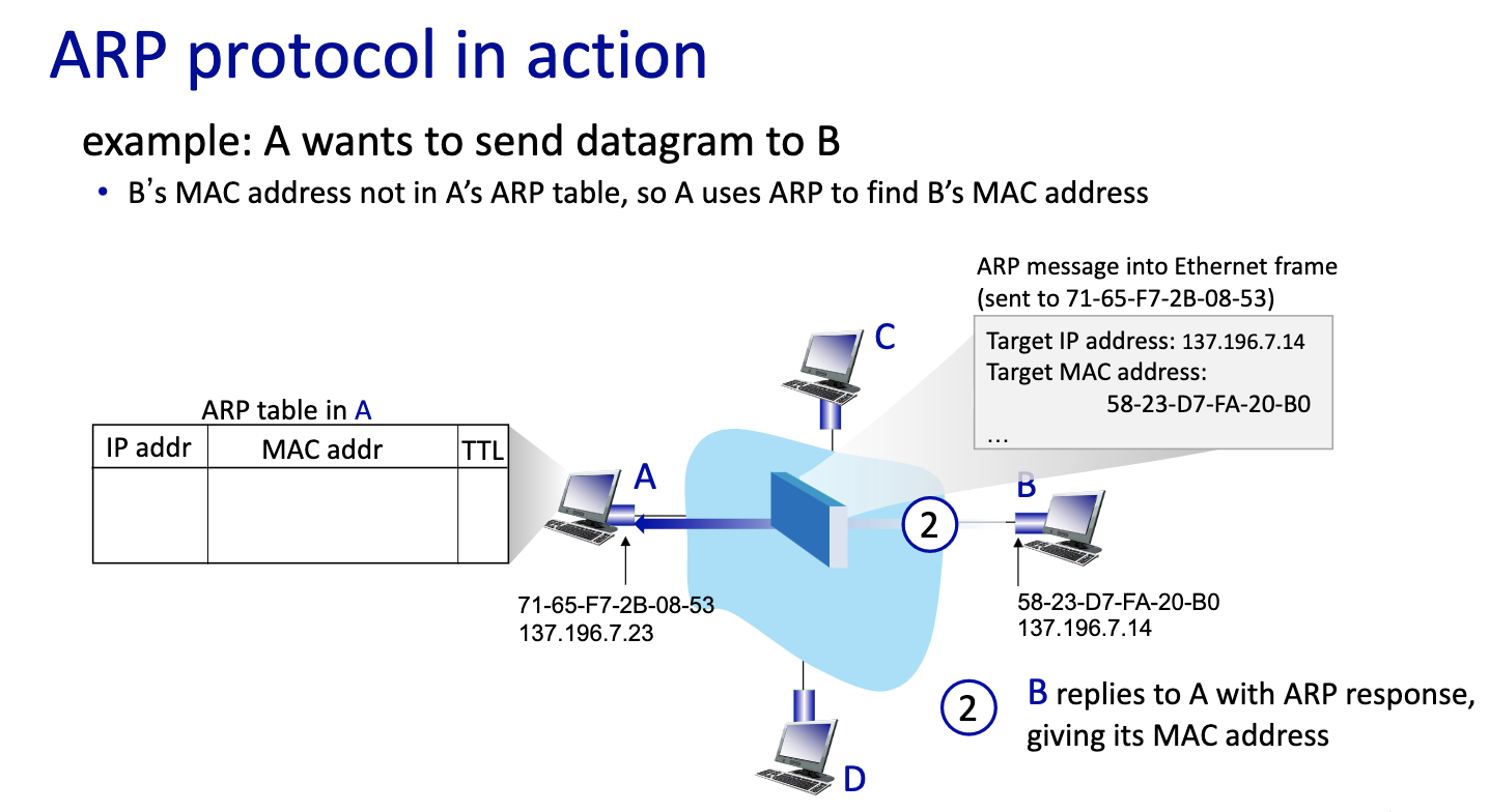
- ARP table per network interface card
- IP address
- MAC address
- Time to Live (TTL)
- Device don’t stay forever on the same LAN (makes sense)
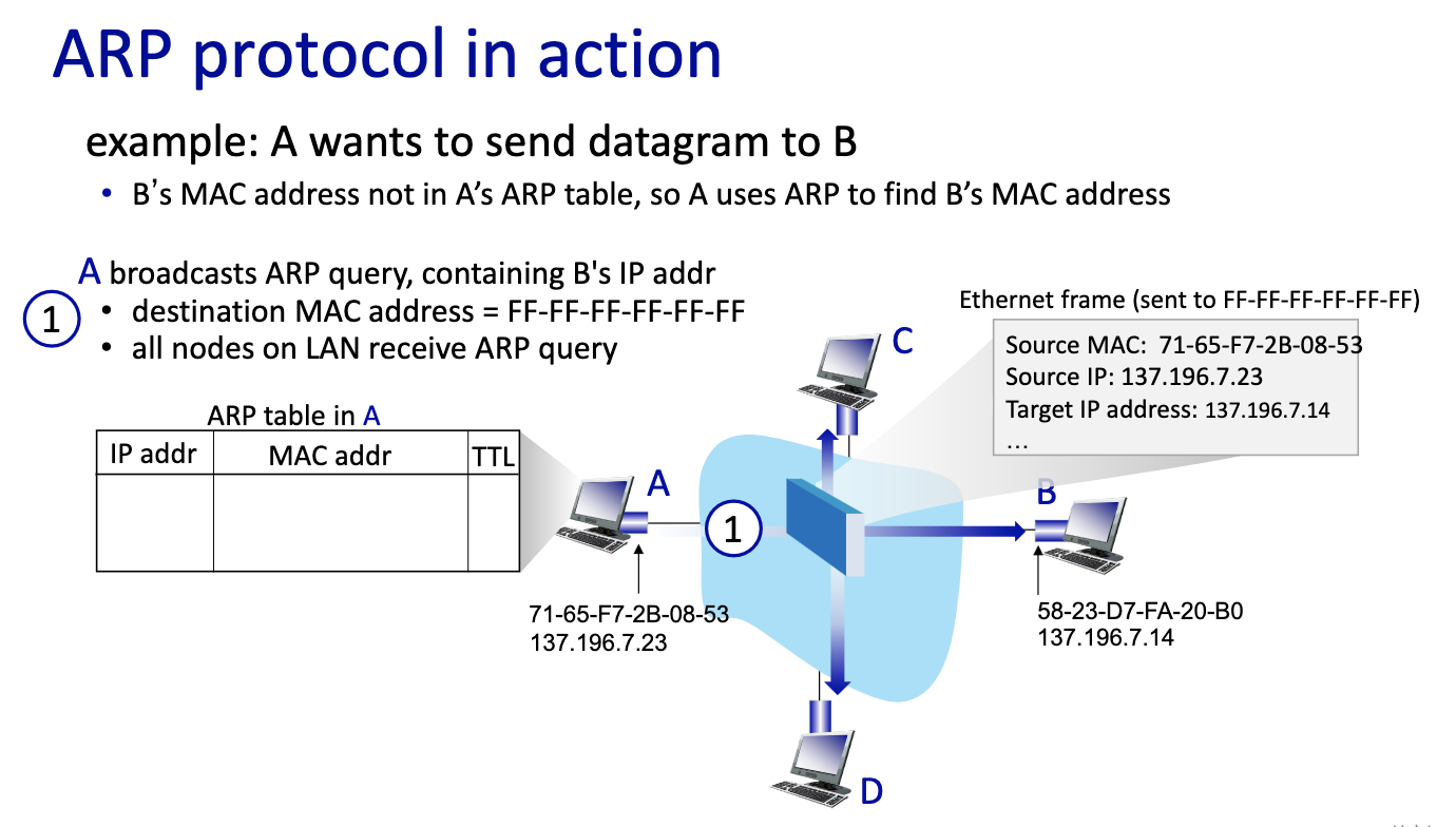
- first message broadcast
- second one
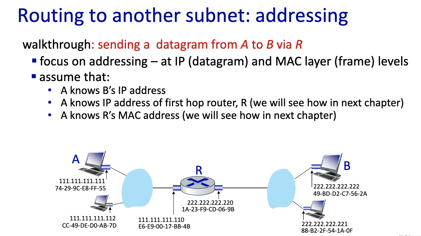
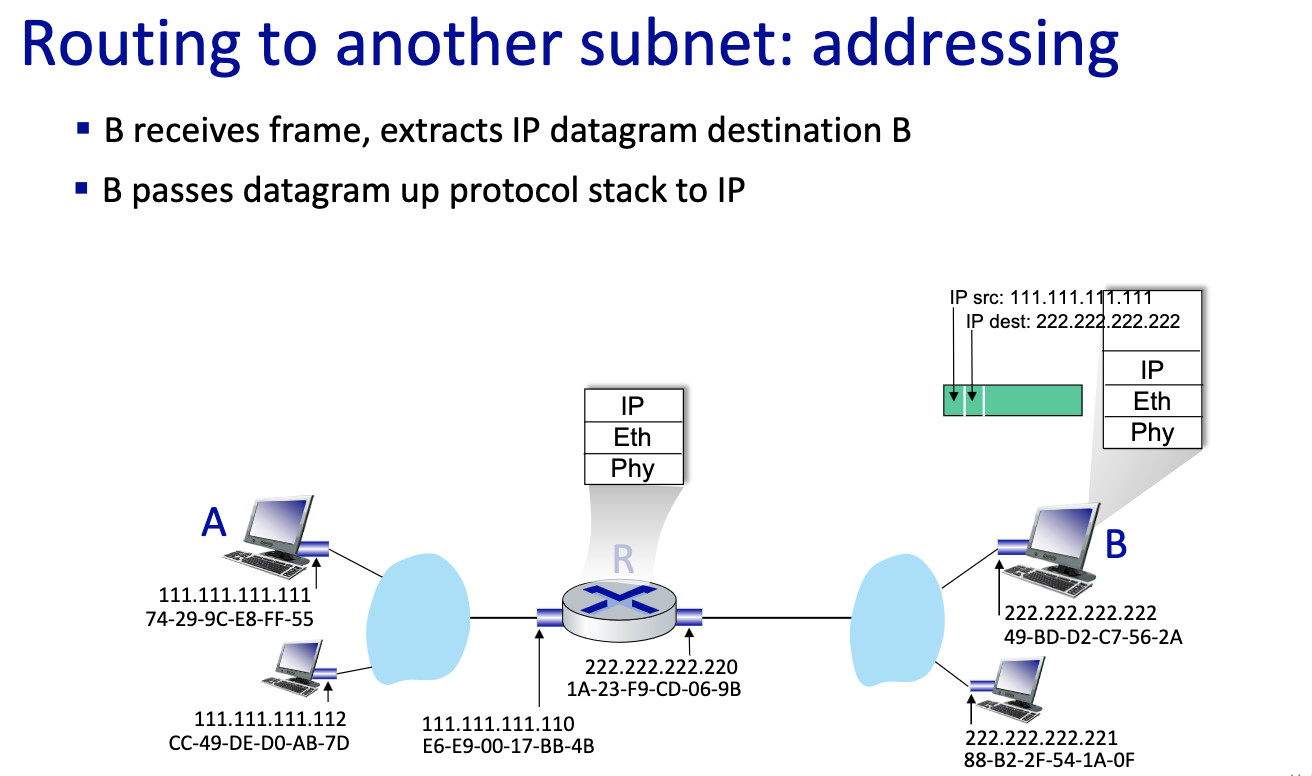
- If B is not on the same LAN
- Send first frame from A to R,
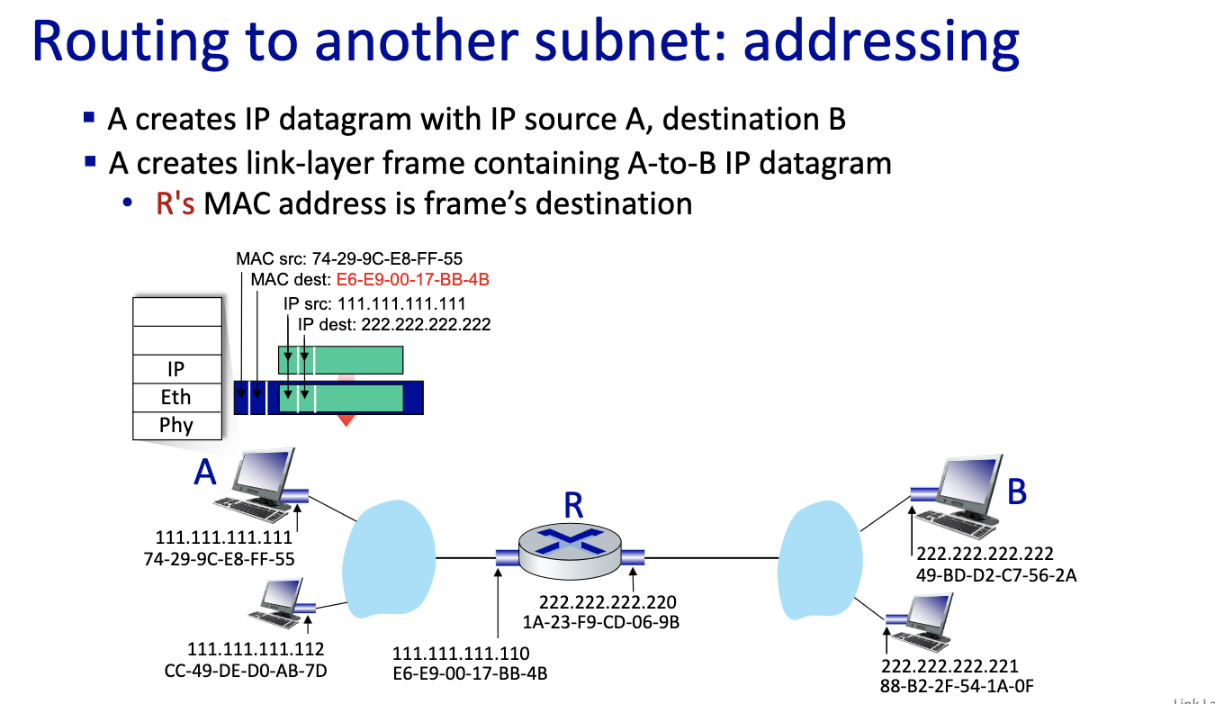
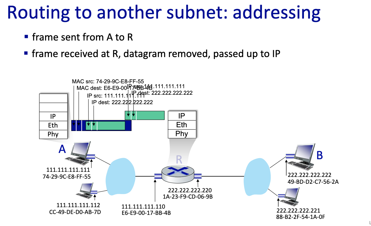
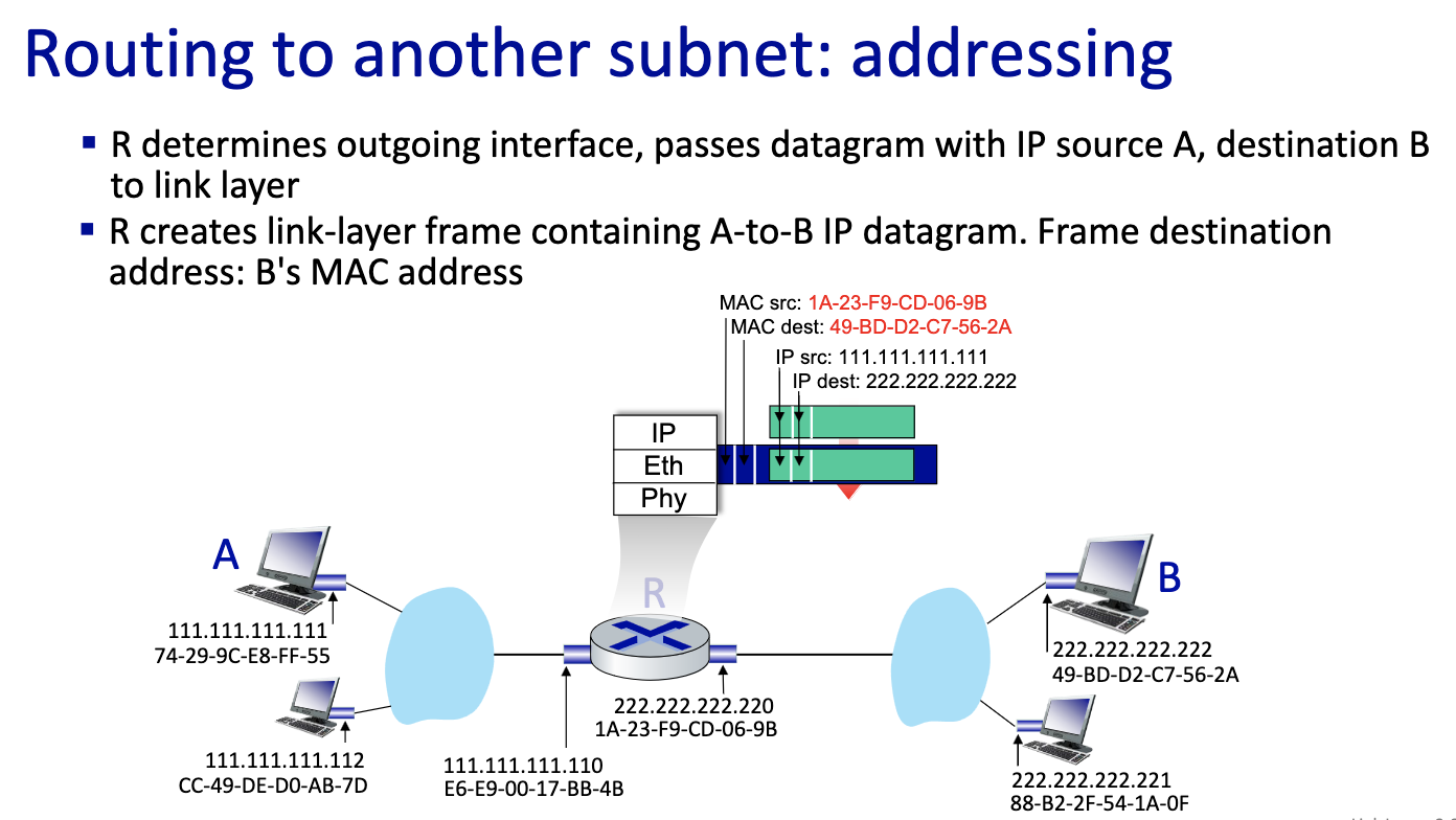
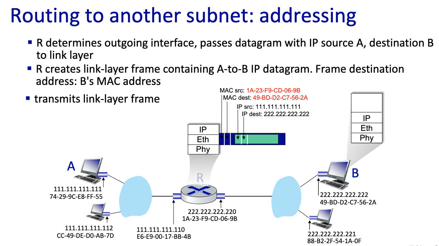
- this is a critical slide ^
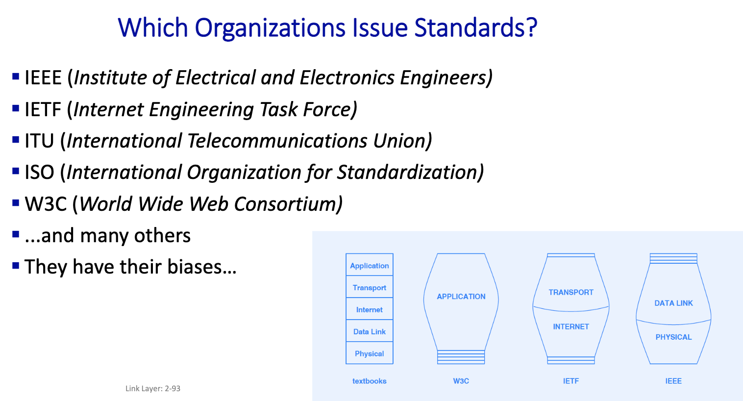
- Each organizations cares about different layers.
Standards Define
- Network topology (shape)
- Endpoint addressing scheme
- Frame (packet) format
- Media access mechanism
- Physical layer aspects and wiring
Ethernet
”dominant” wired LAN technology:
- first widely used LAN technology
- simpler, cheap
- kept up with speed race: 10Mbps - 400 Gbps
- single chip, multiple speeds (e.g., Broadcom BCM5761)
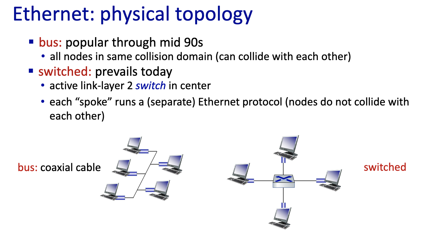
- right picture: new internet has no more shared medium.
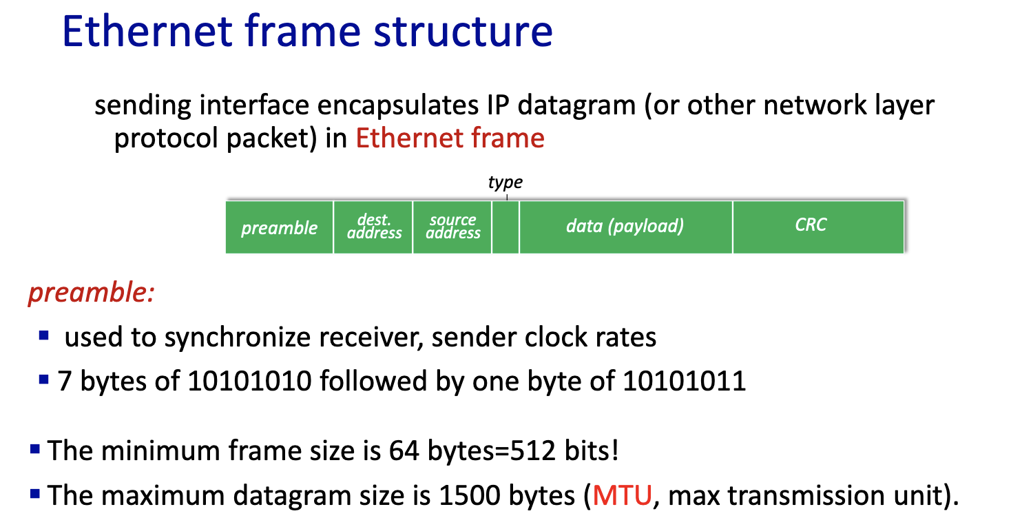
- if datagram is bigger than 1500 bytes in IPv4, it fragments!!!
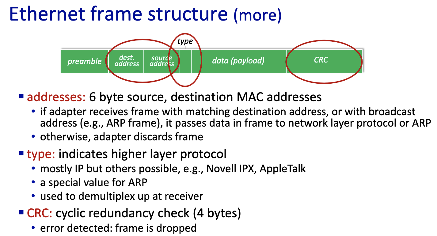
Ethernet: unreliable, connectionless
- connectionless: no handshaking between sending and receiving NICs
- unreliable: receiving NIC doesn’t send ACKs or NAKs to sending NIC
- data in dropped frames recovered only if initial sender uses higher layer rdt (e.g., TCP), otherwise dropped data lost
- Ethernet’s MAC protocol: unslotted CSMA/CD with binary backoff
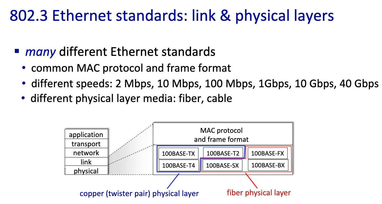
- differ on speed and medium
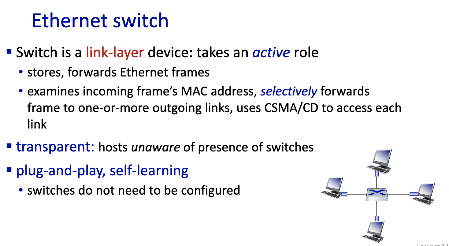
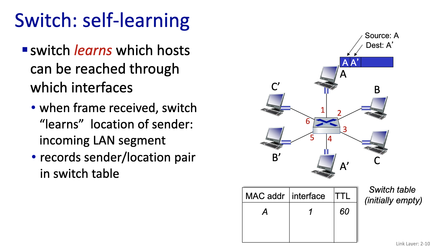
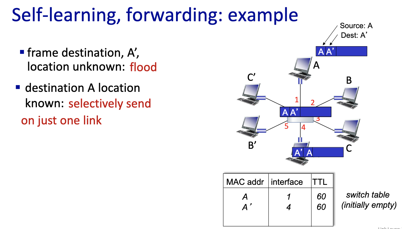
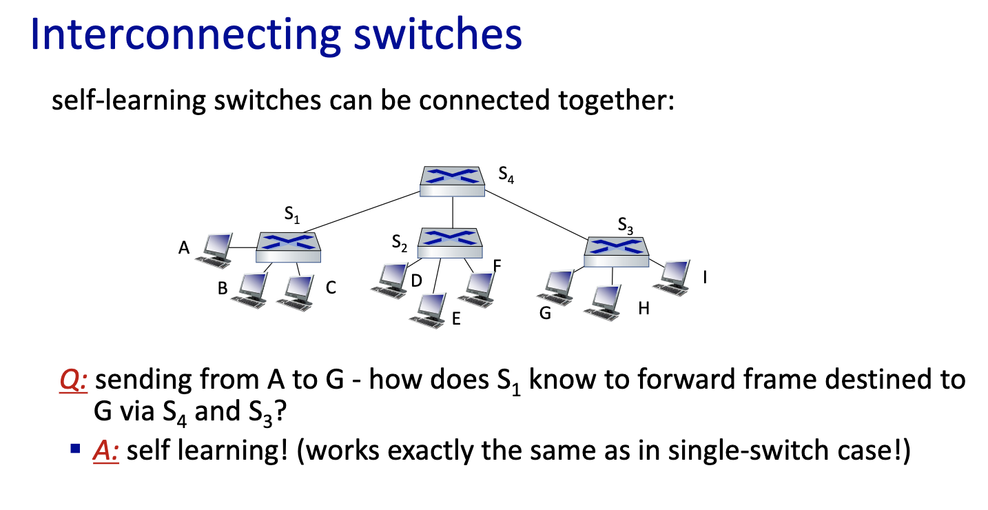
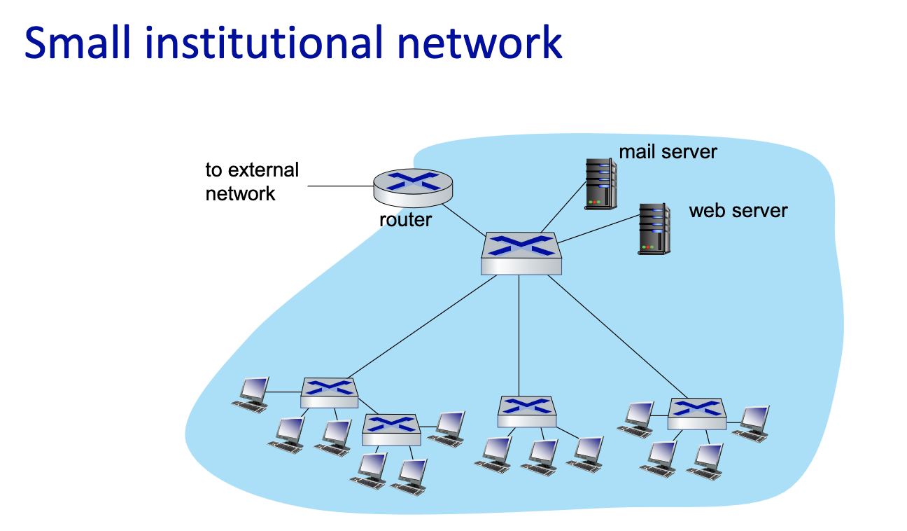
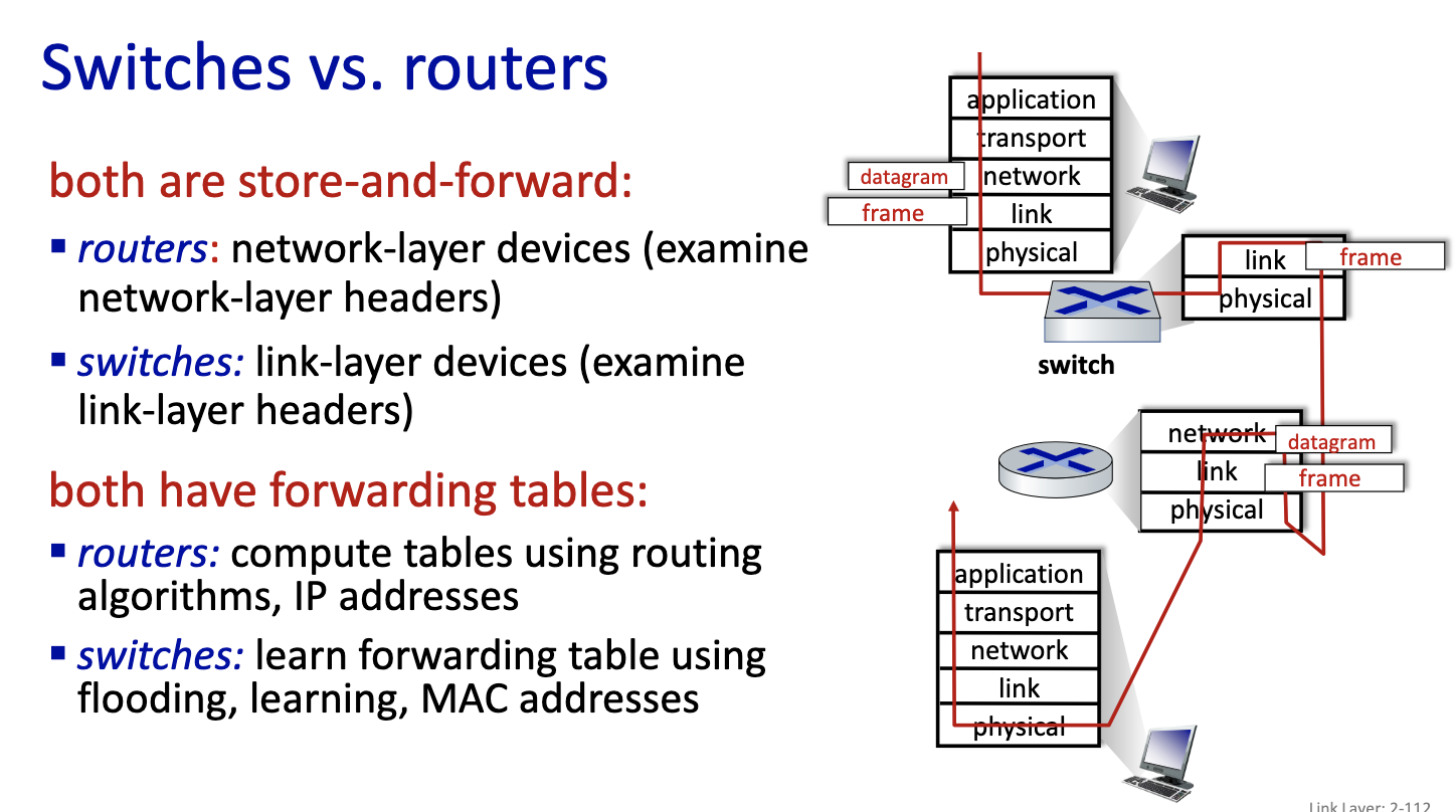
- moving frame, only has layer one and layer2. The switch is a layer 2 device. It stores frame and forward into the right output port. Decides on which link to put it on.
- Does it with MAC addresses and not IP addresses.
- Nodes are not aware of the switches
- since it’s local, the switches can learn.
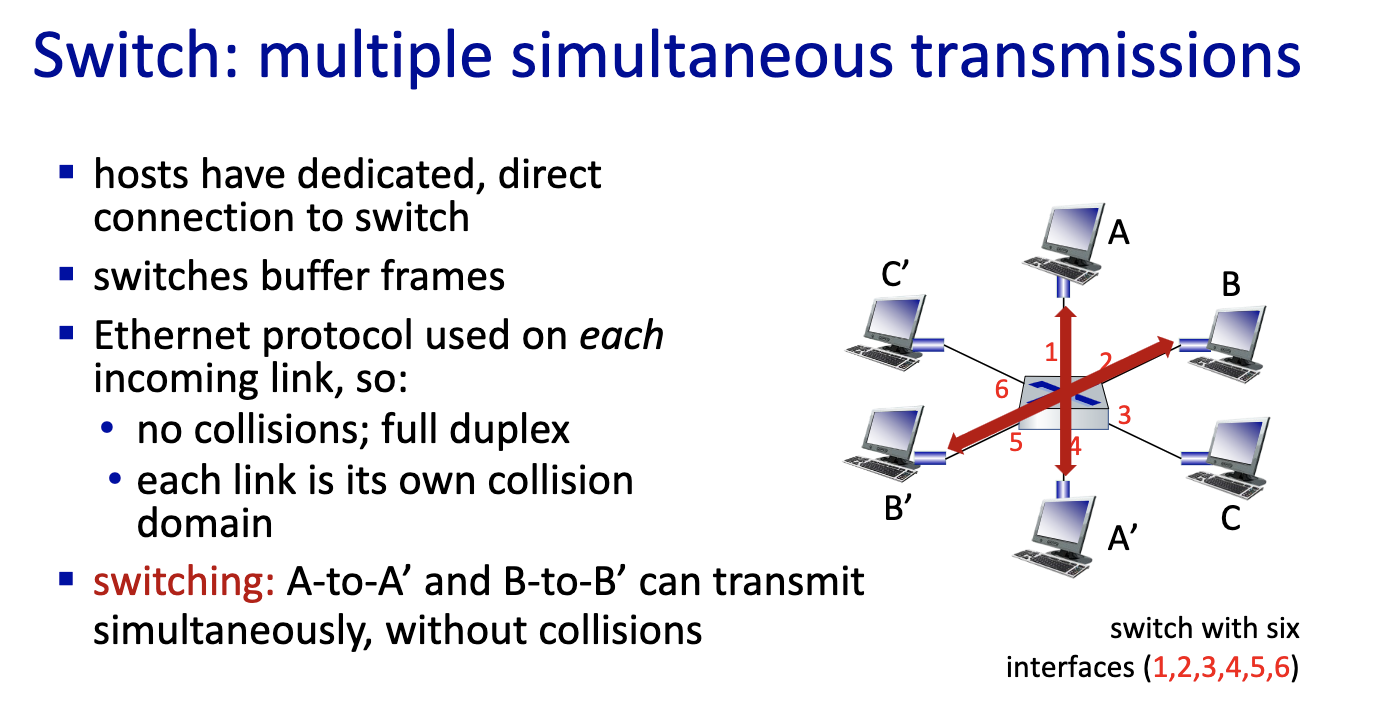
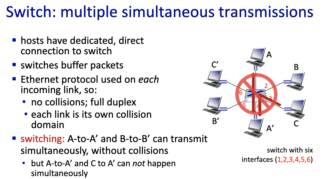
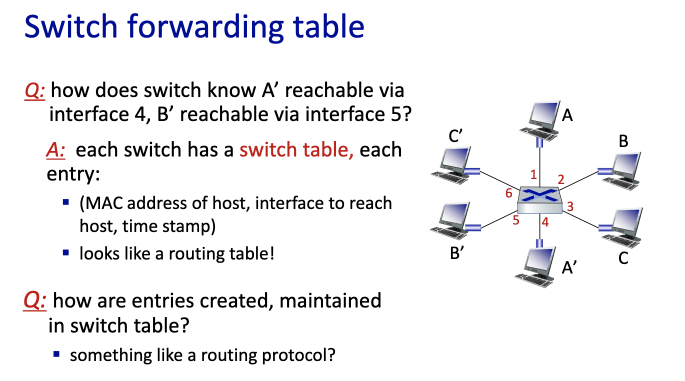
- link layer switches can learn
Chapter 2: Summary
- principles behind data link layer services:
- error detection, correction
- retransmission protocols
- sharing a broadcast channel: multiple access
- link layer addressing
- instantiation, implementation of various link layer technologies
- Ethernet
- switched LANS, VLANs
Chapter 3: Network Layer
Network layer: our goals
- understand principles behind network layer services:
- network layer service models
- forwarding versus routing
- how a router works
- addressing, DHCP
- middleboxes
- routing
- instantiation, implementation in the Internet
- IP protocol, ICMP
- DHCP, NAT (saved IPv4)
- BGP, OSPF …
Network layer: roadmap
- Network layer: overview
- data plane
- control plane
- The data plane: the Internet Protocol
- IPv4: datagram format
- IPv4: addressing
- IPv4: network address translation
- middleboxes
- IPv6
- What’s inside a router?
- The control plane: ICMP, Routing
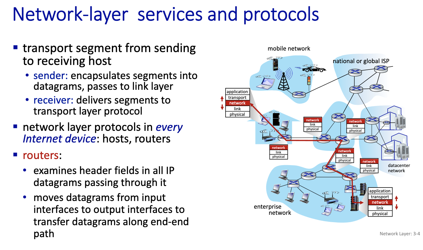
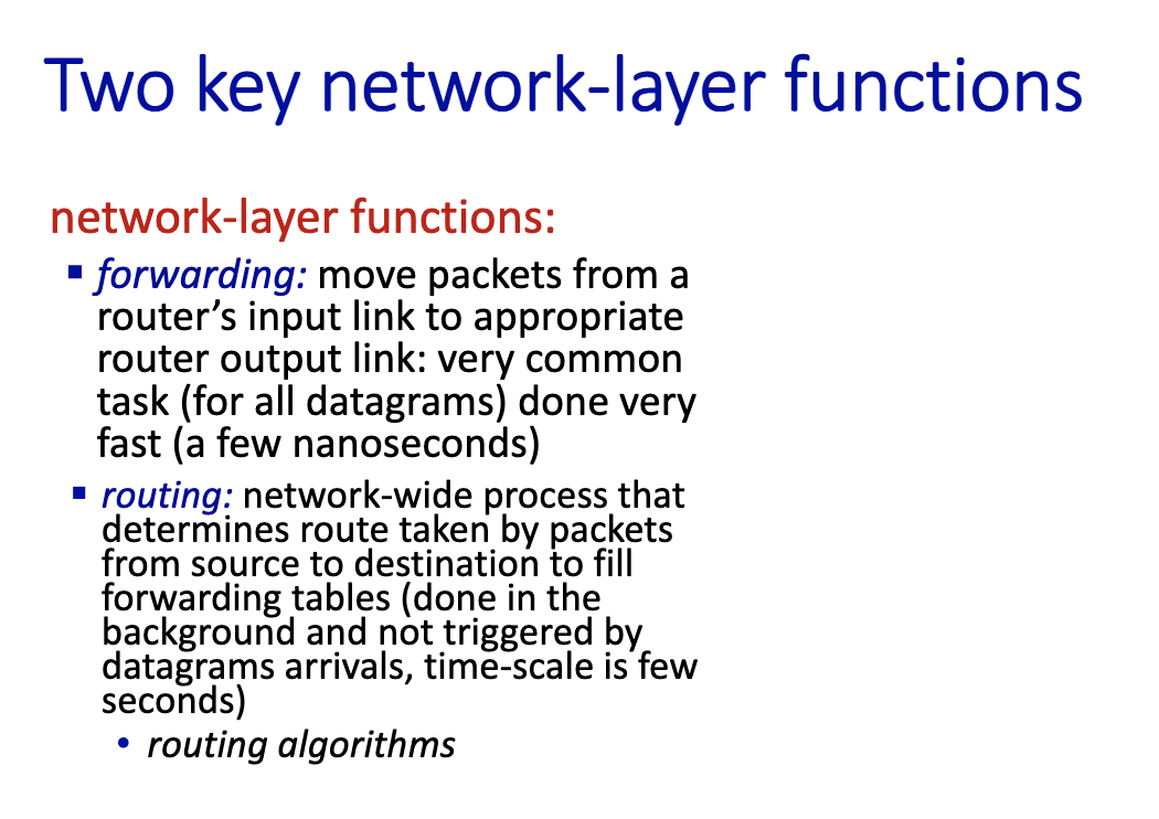
- forwarding is about the datagram
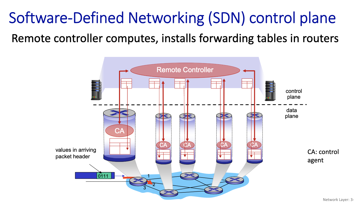
- Routing: asynchronous process done on another level.
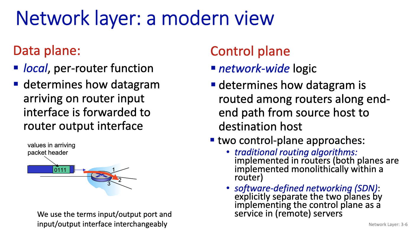
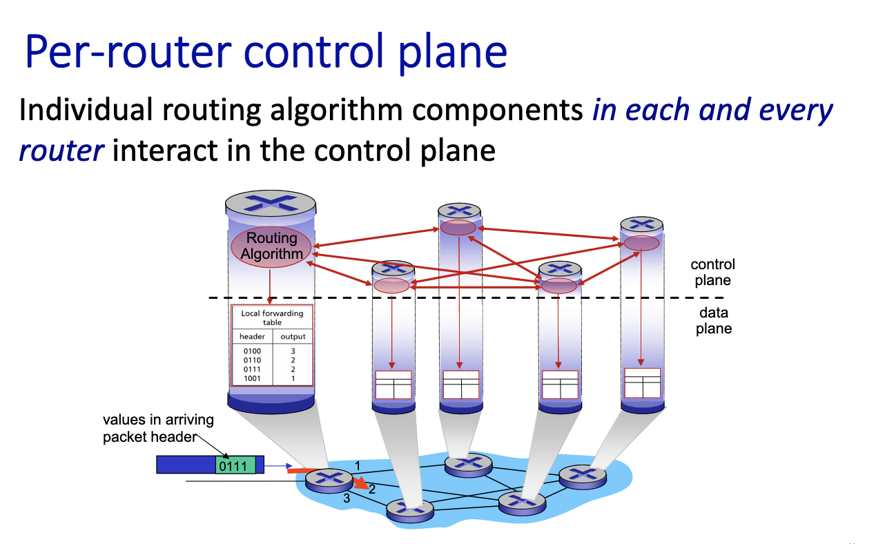
- routers talk to each other on the control plane. asynchrnously, the control plane can change the table
- data place is about reading the table
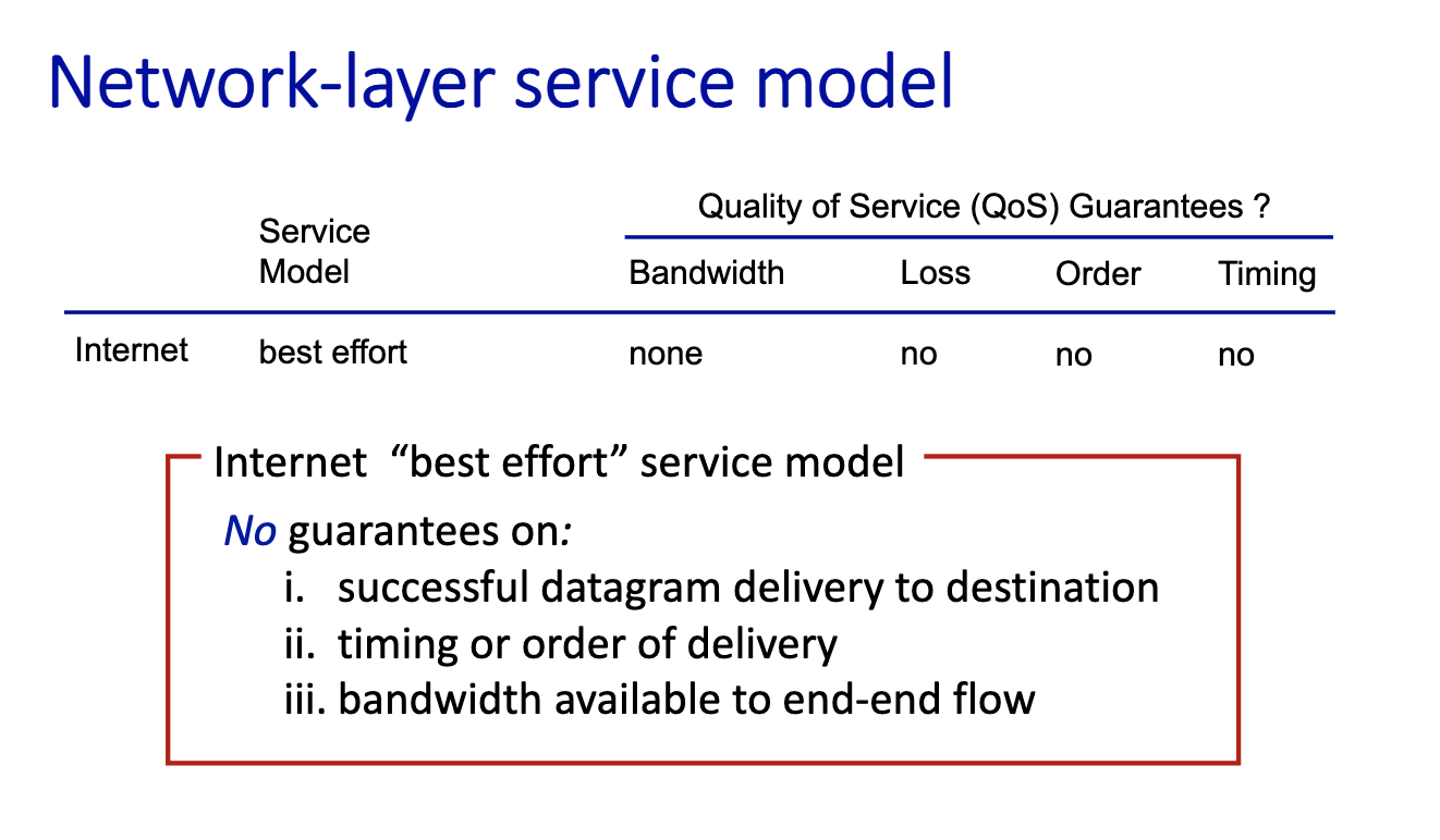
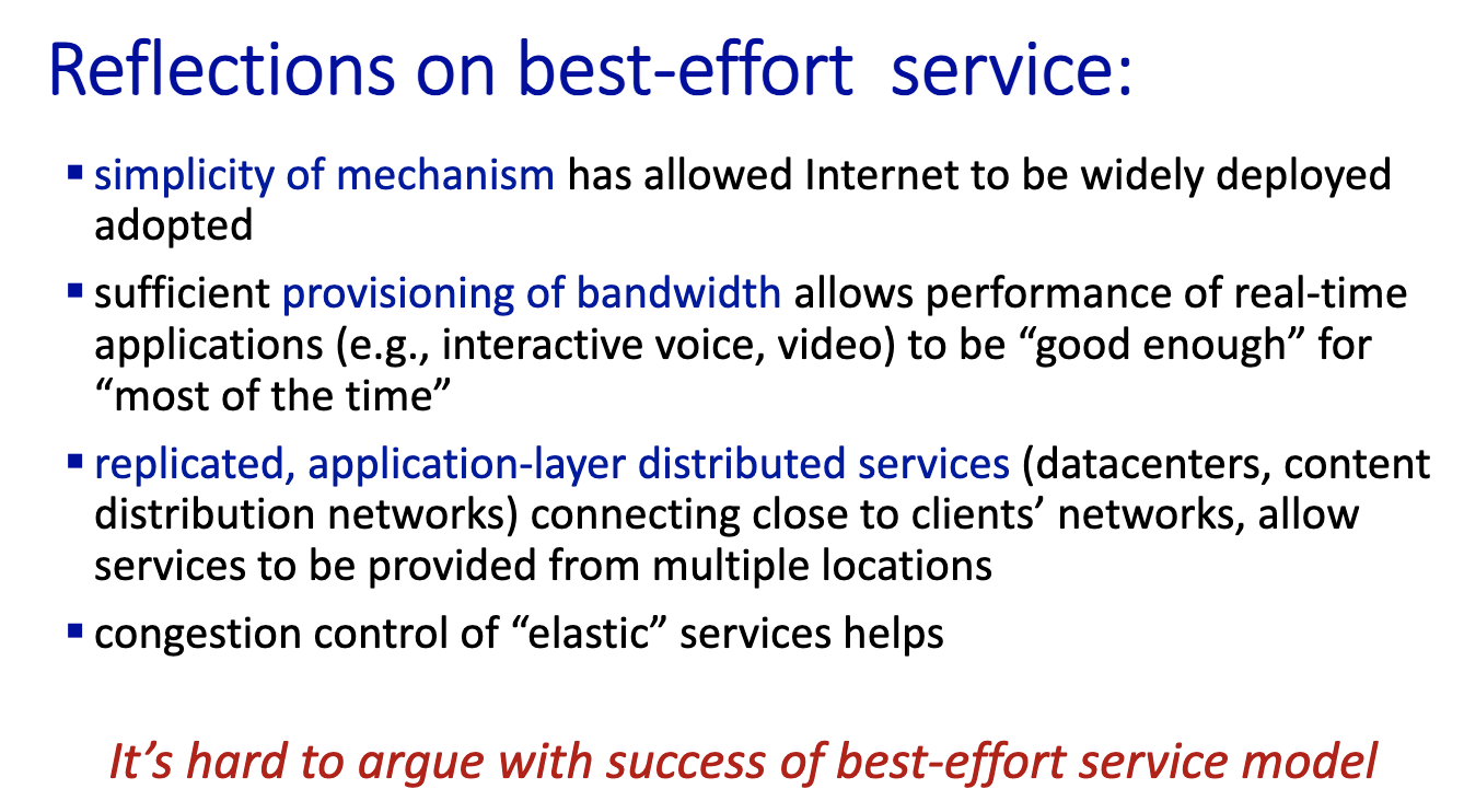
- simplicity means robustness
- provisioning means adding more capacity, more links
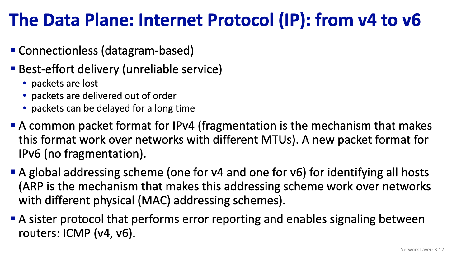
- Connectionless: ethernet, people talk without having to go through an establishment phase. At the IP layer, it is connectionless.
- Define dataplane: say all of this, and also mention sister protocol
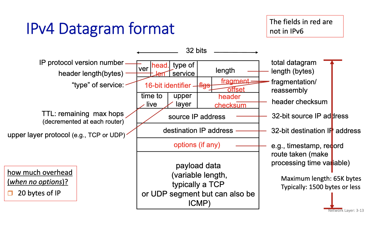
- first datagram created at the host
- Time to live: avoid loops, decrease by one in every hop. when it becomes 0, each router decreases the TTL by one when they receive a datagram, and if its 0, we drop the packet.
- need to compute the header checksum every hop.
- since we are changing the datagram every time, (changing bits, in the header, TTL or fragmentation offset can change)
- We are expected to know this
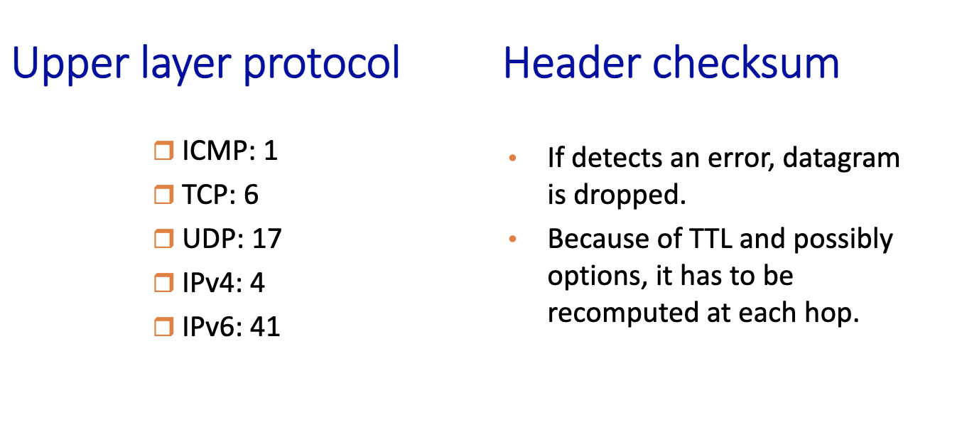
- when its 4: datagram carried in a datagram. Tunneling?
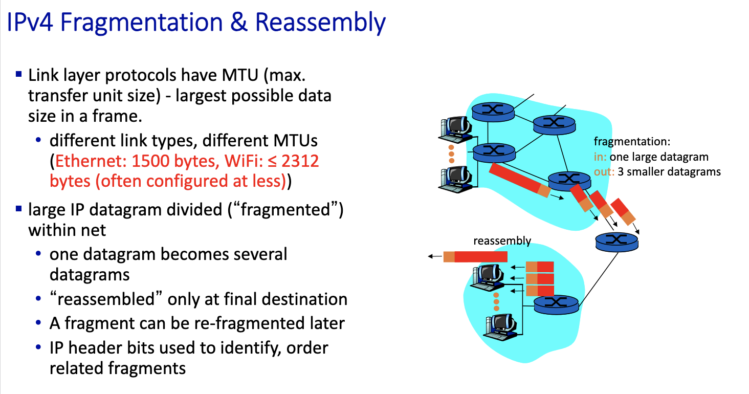
- three fragments are created out of the datagram. have to be reassemble before given to the upper level
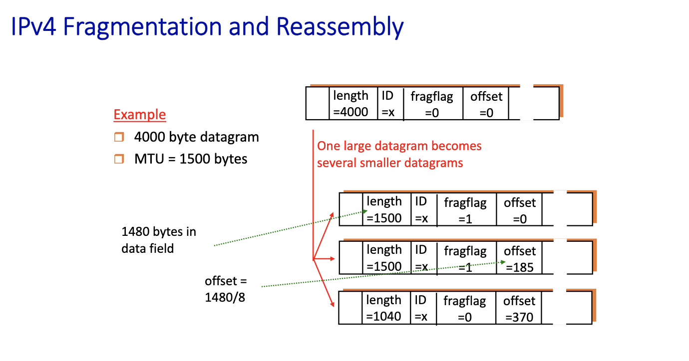
- We create 3 fragments
- say length of each
- carry the same id
- put the flag to 1 on all except the last one, to indicate the last
- offset: saying the first bit corresponds to where
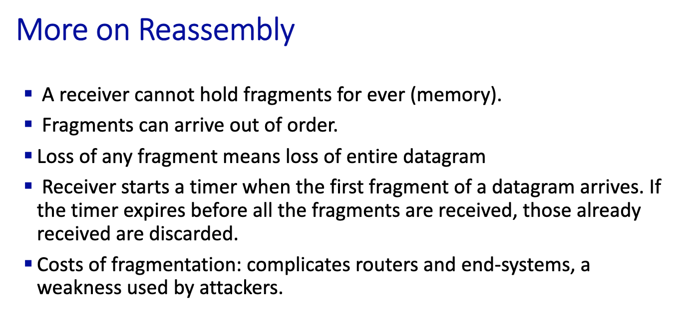
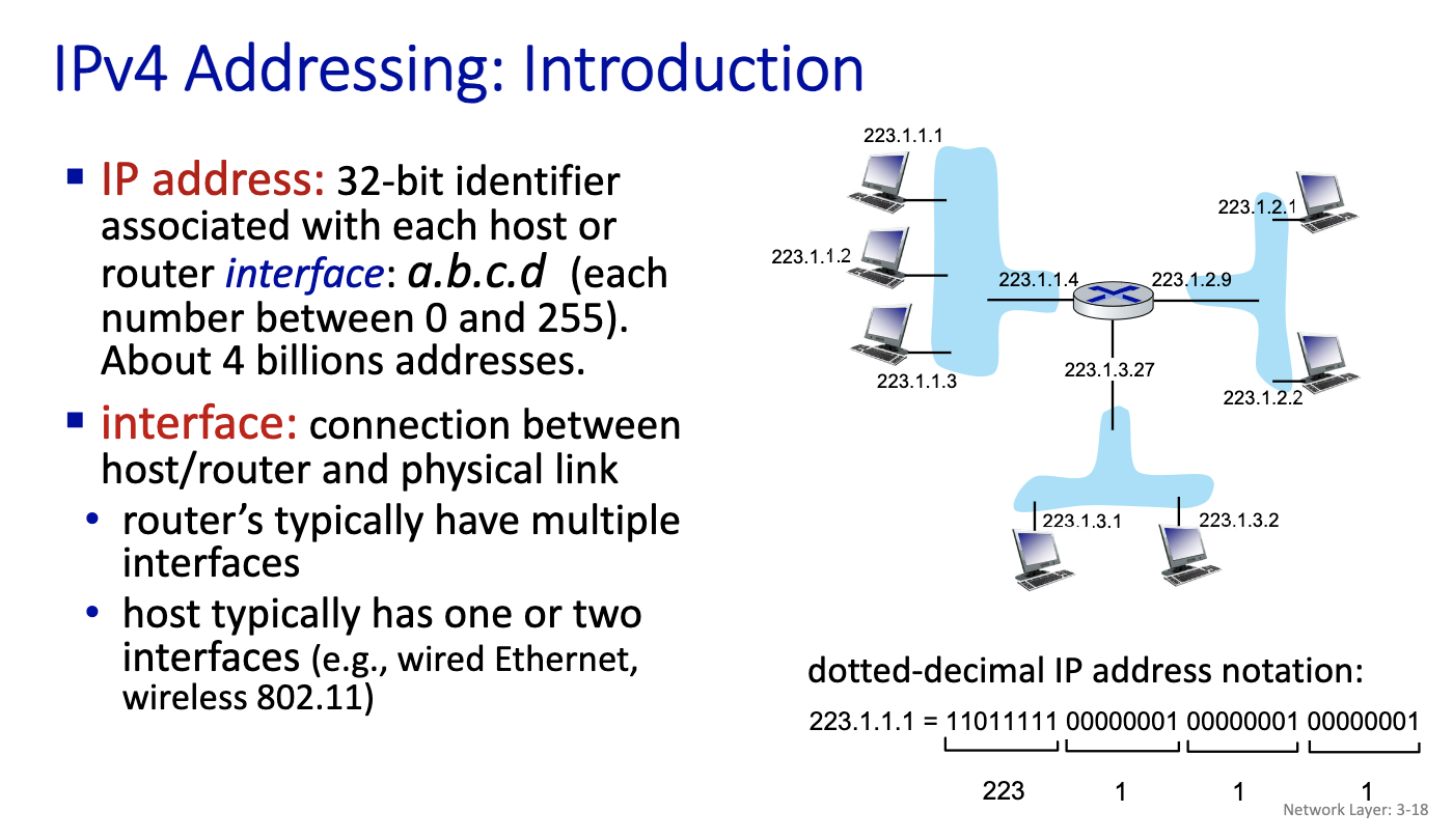
Thu Oct 10
-
ARP: Layer 2
-
Ethernet: Layer 2
-
IPv4 and IPv5: Layer 3
-
DHCP UDP IP : Layer 3, implemented as Layer 5 protocol
-
public IP @ : routable
-
private IP @: NAT
WE ARE IN THE DATA PLANE. We are processing the datagram.
How the routing is filled is in the control plane.
Midterm talk:
- Not difficult if you come to class and listen
- Open ended questions
- describe, give pros and cons
- problems similar to tutorials
- be careful, say right stuff instead of just making up? Be precise. Will prob get part marks
- 4 simple questions on open ended
- 3 problems to solve
- Read the textbook - corresponding chapters
Nov 5 2024
came late. started talking about BGP
- X is a subnet
Nov 13
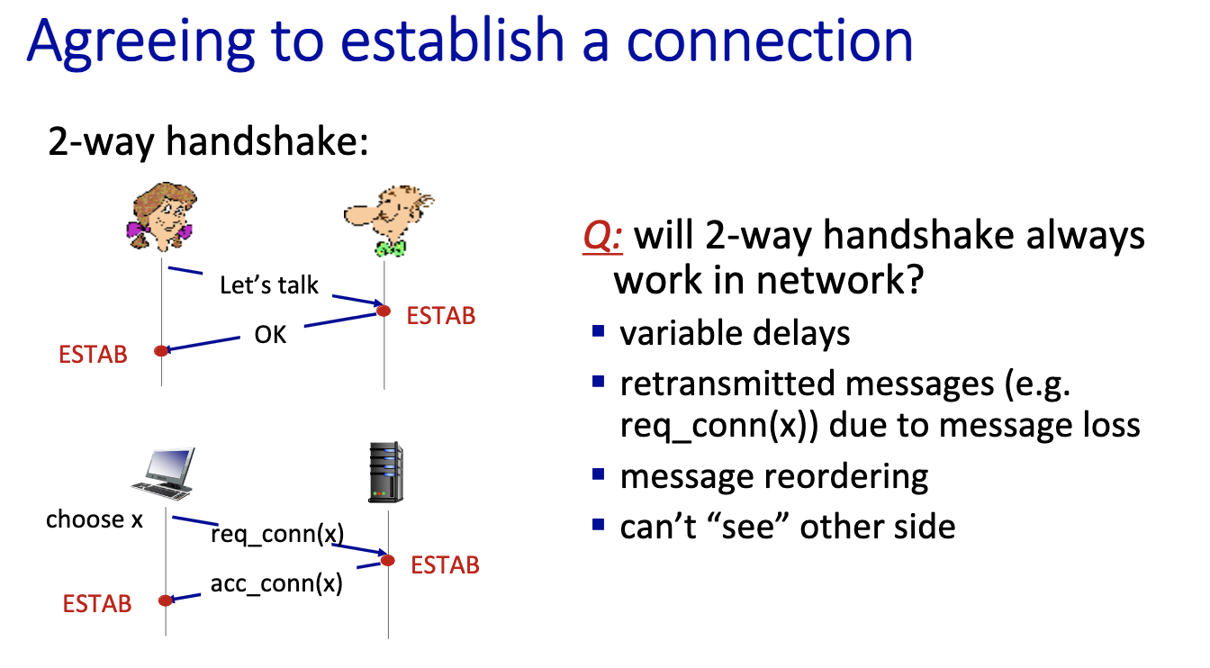
2-way handshake scenarios
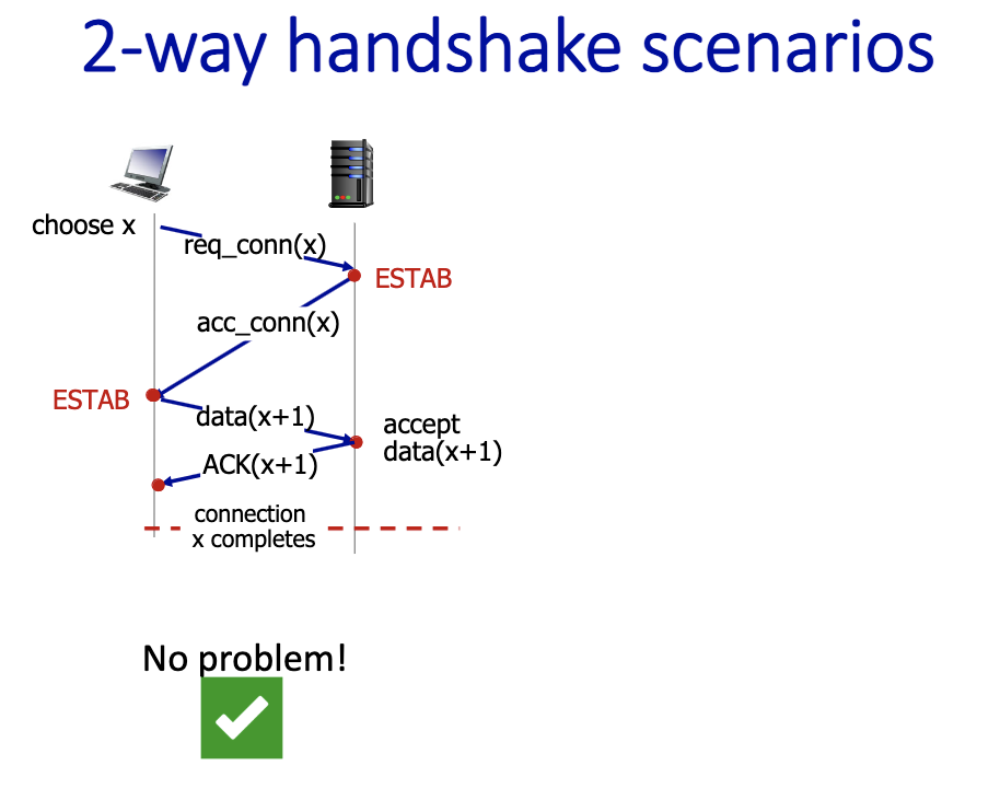
- bad slides???
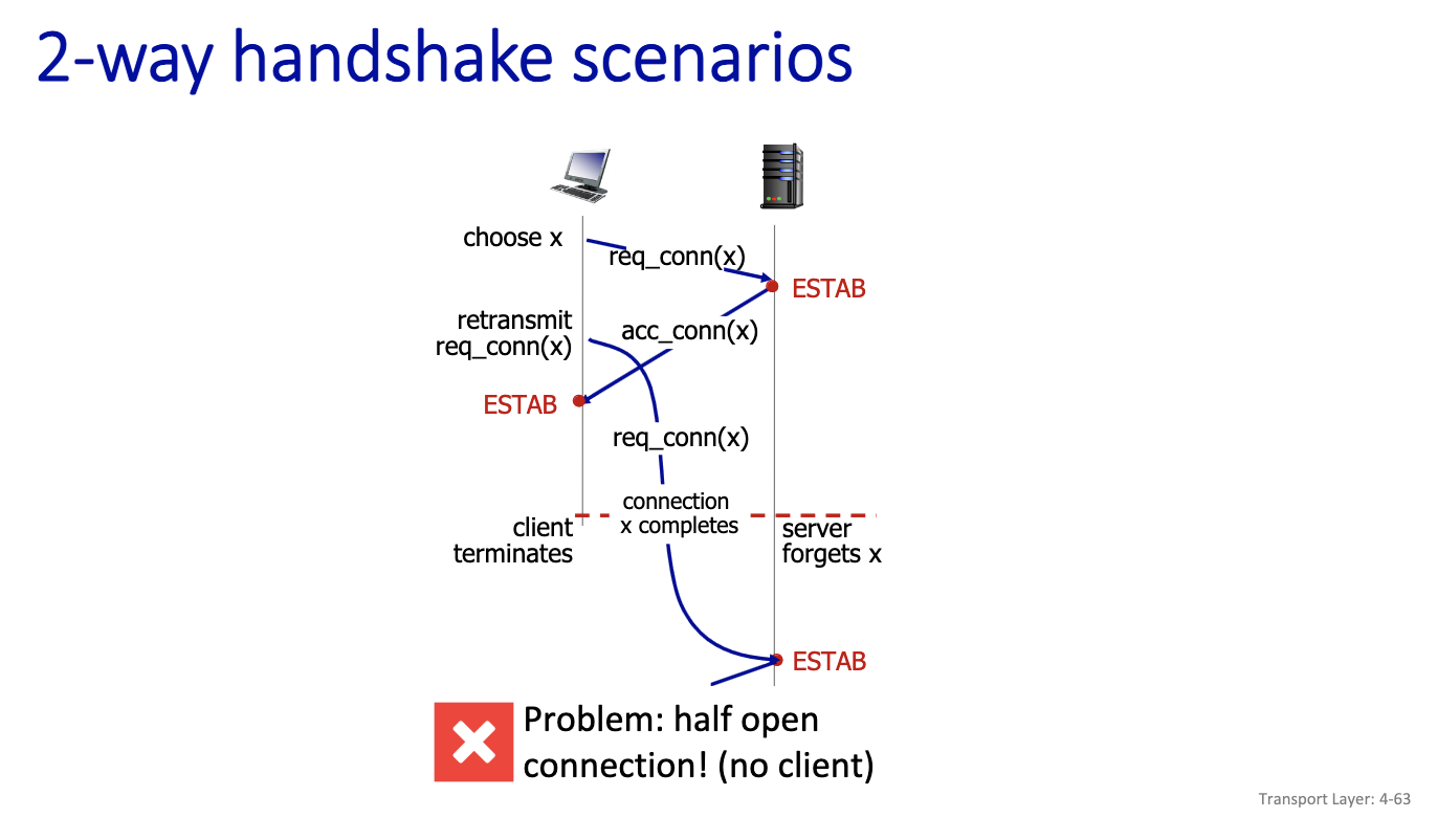
- Half open: no one on the client side to accept the acknowledgement. Client has moved on in this scenario.
TCP’s Startup/Shutdown Solution
- Uses 3 message exchange
- Known as 3-way hadnshake
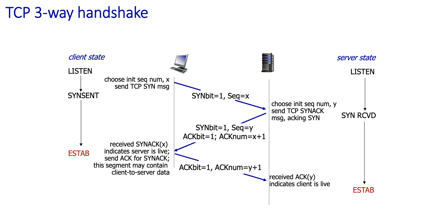
- 2 pure segments without data : first two
- client and server has info about each other on the second message sent
- 3 messages, 3rd one could contain message
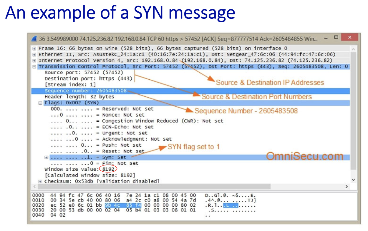
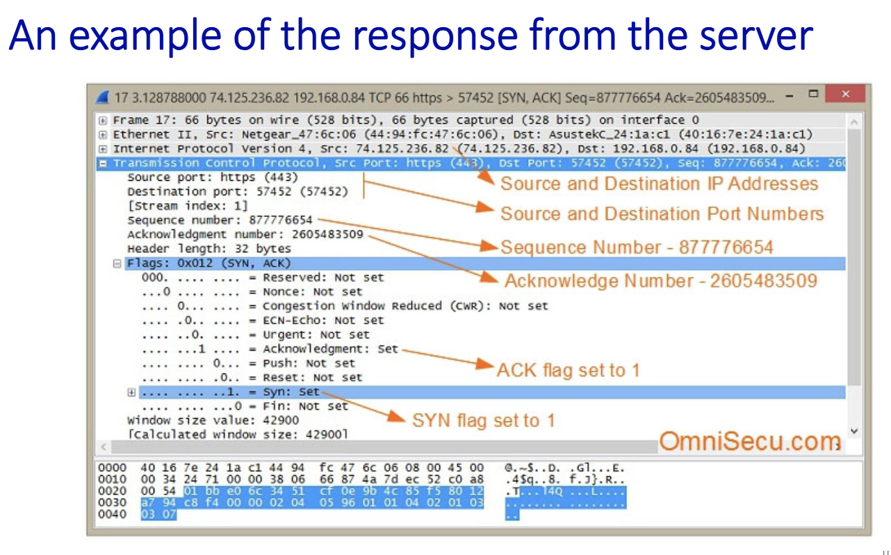
Closing a TCP connection
- client, server each close their side of connection
- send TCP segment with FIN bit = 1
- closing can be difficult → close each half independently, using FIN bit = 1
Congestion Control
Principles of congestion control:
- Congestion:
- informally: “too many sources sending too much data too fast for network to handle”
- manifestations:
- long delays (queueing in router buffers)
- packet loss (buffer overflow at routers)
- different from flow control!
- a top-10 problem!
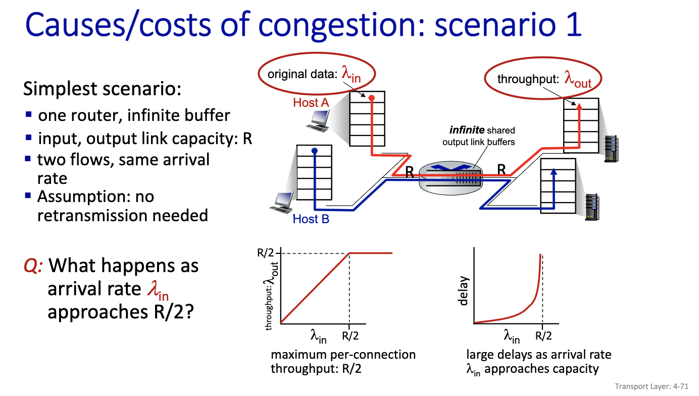
- First model
- Two flows goes through the same infinite buffer with rate R
- No retransmission
- Cannot do better after R/2 (Left diagram is the ideal case)
- Right diagram:
- We have large delay
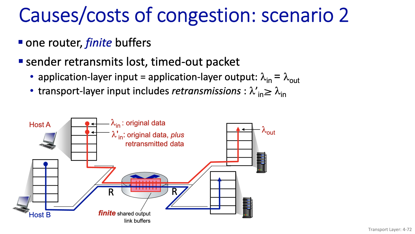
- Lambda’in is larger than lambda in
- Because of retransmission the lambda in at the transport layer will be larger than the lambda in at the application layer
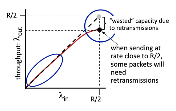
- some packets retransmitted: when rate is low we can have output that is equal to input, but when it’s large, its going to be lower than R/2. gap in the flow.
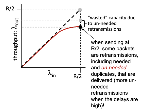
- decrease in output, no collapse
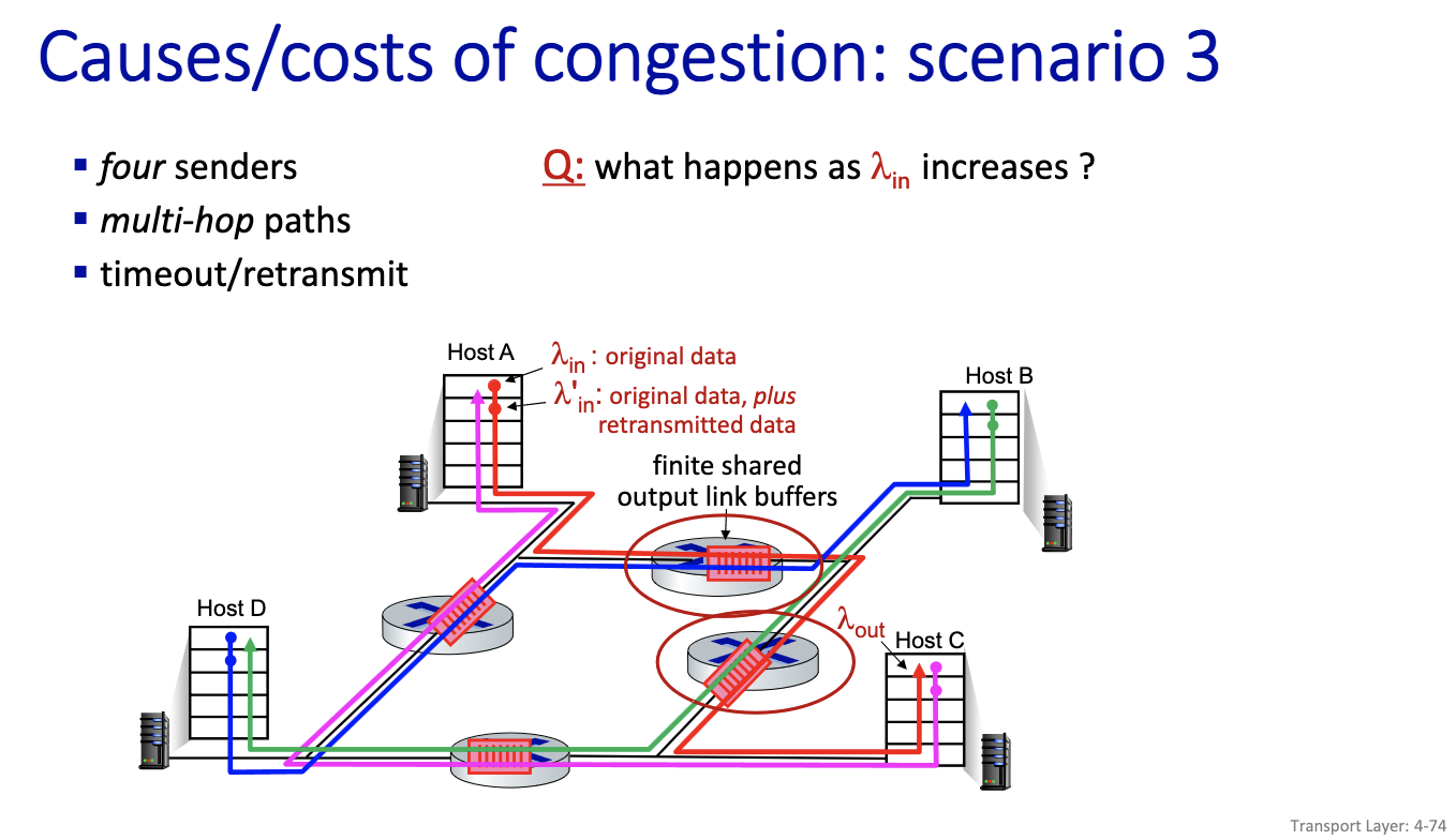
- collapse only seen in this model
- because it’s possible to work on things that ends up being useless. since all of the flow works on the . right traffic can be discarded, some of the packets might be discarded on other flows.
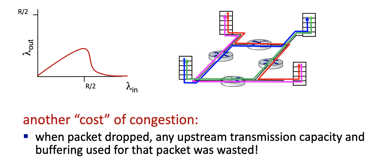
- Nothing comes out! Network is working non-stop.
- Cannot show collapse on a queue. Only with multiple queues, retransmission, long flows and buffer
- TCP is trying to avoid this (diagram on the left)
Insights: Causes/costs of congestion
- throughput can never exceed capacity
- delay increases as capacity approached
- loss/retransmission decrease effective throughput
- un-needed duplicates further decreases effective throughput
- upstream transmission capacity/buffering wasted for packets lost downstream
Approaches towards congestion control
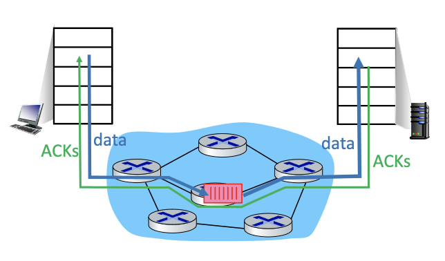 End-end congestion control:
- no explicit feedback from network
- congestion inferred from observed loss, delay → original TCP
- assume “i” created congestion, only based on loss (original TCP)
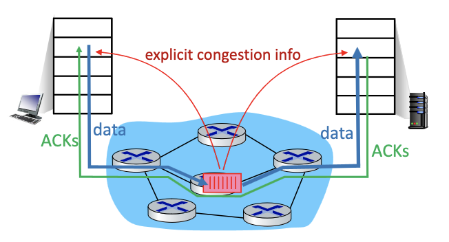
Network-assisted congestion control:
- routers provide direct feedback to sending/receiving hosts with flows passing through congested router.
- will need to pass information in the buffer, but the buffer would have to travel all the way to the server and then back tot he client… for information to provide to the client.
- may indicate congestion level or explicitly set sending rate
TCP congestion control
- TCP uses its window size to perform end-to-end congestion control:
cwndis dynamically adjusted in response to observed network congestion (implementing TCP congestion control) - Recall, the window size is the number of bytes that are allowed to be in flight simultaneously.
- TCP computes window size. big window size: allow a lot of bytes “in-flight”
W = min(cwnd, RcvWindow)CWND: obtained through congestion control: computed internally (we choose how to compute this.)RcvWindow: obtained by flow control: sent on the other side in the TCP header

- Basic congestion control idea: sender controls transmission by changing dynamically the value of
cwndbased on its perception of congestion- increase and decrease cwnd depending on the congestion levels
Note
Due to flow control, the effective window size is
EW = min(cwnd, RcvWindow)
- Slow start and Congestion Avoidance (The 2 phases)
- we start with sending 1 byte, and increase congestion window very fast. prob the network , push the limit, then when the original TCP believes there’s congestion, it backs off. THE KID PRINCIPLE
- Approach: sender increases transmission rate (specifically, its window size, i.e., cwnd), probing for usable bandwidth, until problem (loss event) occurs. When problem is detected, it decreases cwnd.
- By controlling the window size, TCP effectively controls the rate.
- we start with sending 1 byte, and increase congestion window very fast. prob the network , push the limit, then when the original TCP believes there’s congestion, it backs off. THE KID PRINCIPLE


- Saw-tooth behaviour
- indication to back off: A loss!
- By controlling window size, we control the rate!
"Classic" TCP congestion control
- Two “phases”
- Slow Start
- Congestion Avoidance
- important parameters:
cwndssthresh: defines threshold between a slow start phase and a congestion avoidance phase
TCP: slow start (SS)
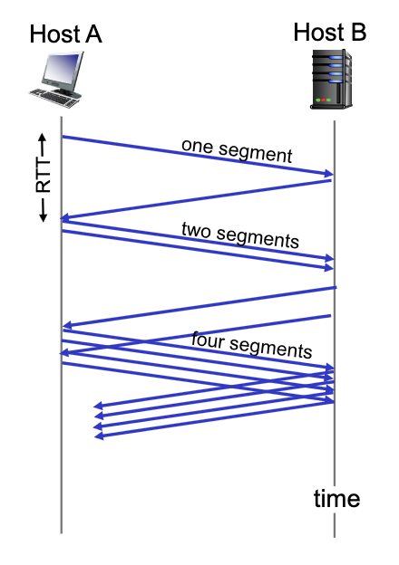
- TCP starts in Slow Start with cwnd = 1 segment and increases the window size as ACK’s are received
- During Slow Start, TCP increases the window fast (typically by one segment for every ACK that is received)
- When cwnd = ssthresh, TCP goes to Congestin Avoidance phase.
Note
Typically, during slow start cwnd doubles every round trip time: exponential increase (assuming each segment is acked!)
TCP: from slow start to congestion avoidance
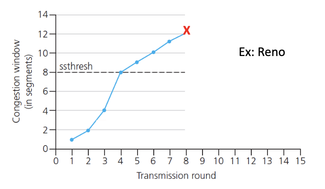
- When we get a loss: set threshowd to 1/2 of latest value of cwnd. and decrease cwnd.
- Basically update the parameters
TCP: Congestion Avoidance
- TCP is most of the time in this mode
- During congestion avoidance, tcp increase the window slower
- Depends on the version of TCP
- One segment per RTT (linear increase)
Congestion detection and reaction to congestion
- 3 duplicate ACK’s could be due to temporary congestion
- Timeout: not enough ACK received
- loss: decrease window size: depends on loss event
- TCP Reno example of the implementation
- If Timeout happens, ssthresh = cwnd/2, and set cwnd = 1, and go to the Slow Start phase
- If 3 duplicate ACKs occur cwnd = ssthresh = cwnd/2 and stays in the phase. → Fast recovery
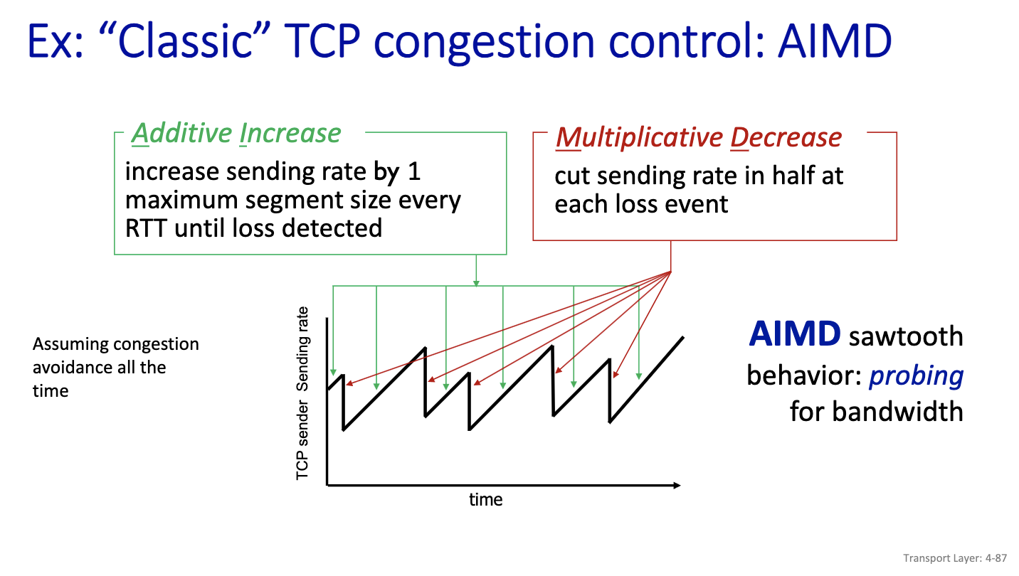
- For 3 Duplicate scenario
- Additive increase increases linearly
- Decreases multiplicatively. (just as shown in the diagram) AIMD has been the solution for tcp congestion control for a long time. Except we have a better way today.
Thu Nov 21, 2024: finish Chapter 4
Why 2 way handshake in TCP would not work?
- server forgets about the client, when the client tries to retransmit, but the server would think its a new
congestion control→ TCP
compute internally the congestion window, which is the w = min(cwnd, receive window(flow control))
slow start, congestion avoidance
2 main char of TCP:
- decide base on losses → indication of congestion is losses (event are loss based)
- 3 losses
- timeout → major event
- AIMD (Additive Increase Multiplicative Decrease)
- Is additive increase a great idea??
Not a a good idea that it is based on losses:
- when losses occur → already too late
- wireless can cause losses!
- punished twice because tcp would think that it’s a congestion → back off
- bad bit/rate
Why AIMD?
First successful attempt: TCP CUBIC
- we increase faster at the beginning and get more careful when we get closed to w_max. don’t use linear increase
- probe faster between w_max/2 and w_max.
- so we get a better rate: congestion window (blue)/window
Google came up with detecting congestion based on delay. They created TCP BBR (unfair to others, it just grabs more)
- Idea is do the measurement of RTT (assume path is stable that is if your routing is relatively stable)
- Minimum RTT give an idea of the rate in the base case. Then measure current RTT.
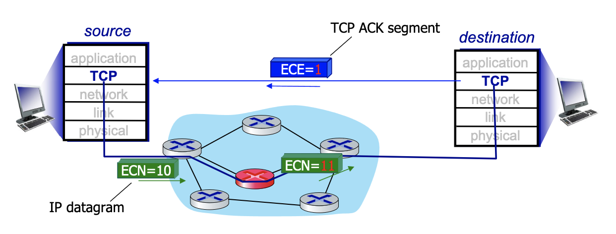
Explicit congestion notification (ECN)
- Another way to detect congestion
- Operator (think Rogers) decides if they use ECN
- Mark IP header →IP datagram with 2 bits when there is a problem (router don’t know anything about the TCP). But still putting 2 bits, mark all packets 11 if there is a problem. Which is going to TCP layer of destination. And destination is put the bit on ACK segment (layer 4 TCP) to say there’s explicit congestion
TCP Fairness
- TCP loop differs, we have different sizes of loop, distance between client and server
- Is AIMD fair?
- In the case with 1 link, similar identical connection
Is TCP Fair?
Example: two competing TCP sessions with same RTT on bottleneck link of rate 10 segments per RTT.
- If we send less than 10 segments we good, otherwise we backoff
- Whole point is to get to a window size that is equal between the two
- Fair is R/K = same rate?
Evolution of transport-layer functionality
- since
cwndis computed internally, its really hard to measure
EXAM:
- should be able to recognize: slow start, AIMD, cubic → visually
Wifi
Spectrum
- Best bands are in the lower region. But limited space.
- Frequency reuse
Two Types of Bands
- Licensed
- Unlicensed
Tue Nov
