Congestion Control
Principles of congestion control
Congestion:
- informally: “too many sources sending too much data too fast for network to handle”
- manifestations:
- long delays (queueing in router buffers)
- packet loss (buffer overflow at routers)
- different from flow control!
- a top-10 problem!
Congestion control vs. flow control
congestion control: too many senders, sending too fast
flow control: one sender too fast for one receiver
Causes/costs of congestion
Scenario 1
Simplest scenario:
- one router, infinite buffer
- input, output link capacity:
- two flows, same arrival rate
- Two flows goes through the same infinite buffer with rate R
- Assumption: no retransmission needed
- Result: Cannot do better after R/2 (Left diagram is the ideal case)
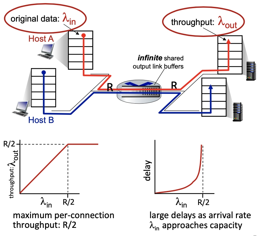
- : rate at which the data arrives at the router from host A
- : the throughput, or rate at which data leaves the router to host B
- R: the link capacity for both input and output
- Graph (on the left)
- remains constant at R/2 as long as is less than or equal to R/2
- when exceeds R/2, cannot increase because the link is at full capacity
- Graph (on the right - delay)
- delay graph shows that delay remains low and manageable as long as is significantly less than R/2
- as approaches R/2, the delay increases exponentially because the router buffer fills up, and packets must wait longer to be transmitted
What happens as arrival rate
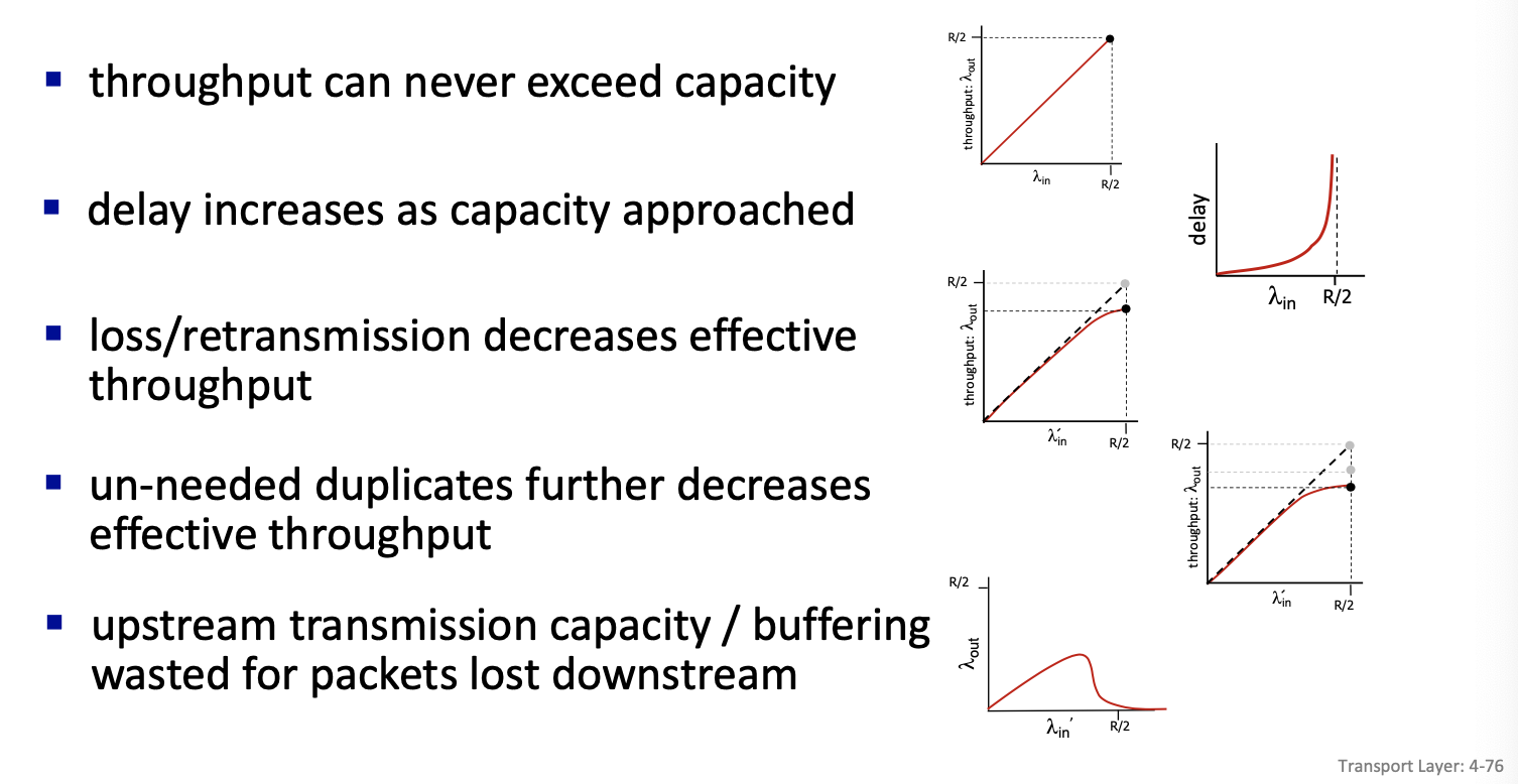
\lambda_{in}approaches R/2?As the arrival rate approaches R/2, the router’s output capacity is maximally utilized, leading to increased queueing in the router’s buffers. This results in significantly longer delays for packet transmission. If exceeds R/2, it cannot be fully processed due to the capacity limit, potentially causing further delays and increased risk of buffer overflow if the buffers are not indeed infinite.
Scenario 2
- one router, finite buffers
- sender retransmits lost, timed-out packet
- application-layer input = application-layer output:
- transport-layer input includes retransmissions:
- Because of retransmission the lambda in at the transport layer will be larger than the lambda in at the application layer
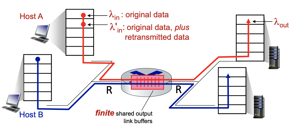
Realistic scenario:
- packets can be lost, dropped at router due to full buffers - requiring retransmissions
- but sender can also time out prematurely, sending two copies, both of which are delivered
”costs” of congestion:
- more work (retransmission) for given receiver throughput
- unneeded retransmissions: link carries multiple copies of a packet
- decreasing maximum achievable throughput
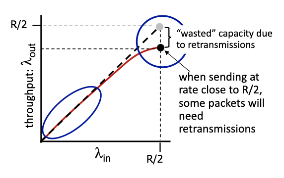
- some packets retransmitted: when rate is low we can have output that is equal to input, but when it’s large, its going to be lower than R/2. gap in the flow.
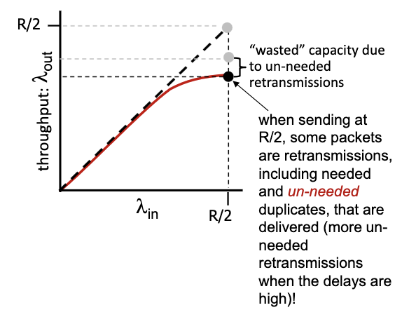
- decrease in output, no collapse
Scenario 3
- four senders
- multi-hop paths
- timeout/retransmit
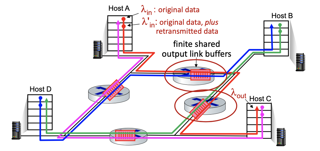
- collapse only seen in this model
- because it’s possible to work on things that ends up being useless. since all of the flow works on the . right traffic can be discarded, some of the packets might be discarded on other flows.
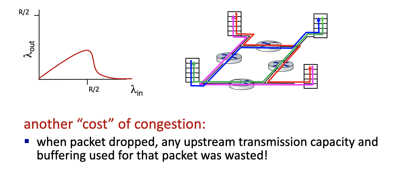
- Nothing comes out! Network is working non-stop.
- Cannot show collapse on a queue. Only with multiple queues, retransmission, long flows and buffer
- TCP is trying to avoid this (diagram on the left)
What happens as
\lambda_{in}increase?
Causes/costs of congestion: insights
Approaches towards congestion control
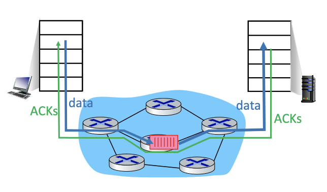
End-end congestion control:
- no explicit feedback from network
- congestion inferred from observed loss, delay
- approach taken by classic TCP
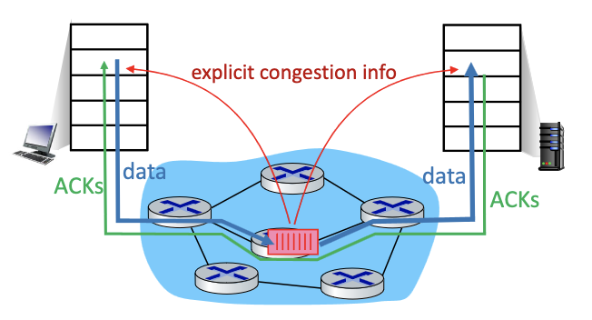
Network-assisted congestion control:
- routers provide direct feedback to sending/receiving hosts with flows passing through congested router
- may indicate congestion level or explicitly set sending rate
- TCP ECN, ATM, DECbit protocols
TCP congestion control
- TCP uses its window size to perform end-to-end congestion control:
cwndis dynamically adjusted in response to observed network congestion (implementing TCP congestion control) - Recall, the window size is the number of bytes that are allowed to be in flight simultaneously
- TCP computes window size. big window size: allow a lot of bytes “in-flight”
W = min(cwnd, RcvWindow)cwnd: obtained through congestion control: computed internally (we choose how to compute this.)RcvWindow: obtained by flow control: sent on the other side in the TCP header

- Basic congestion control idea: sender controls transmission by changing dynamically the value of
cwndbased on its perception of congestion- increase and decrease cwnd depending on the congestion levels
Note
Due to flow control, the effective window size is
EW = min(cwnd, RcvWindow)
Approach
- Slow start and Congestion Avoidance (The 2 phases)
- we start with sending 1 byte, and increase congestion window very fast. prob the network for usable bandwidth, push the limit, then when the original TCP believes there’s congestion, it backs off. THE KID PRINCIPLE
- Approach: sender increases transmission rate (specifically, its window size, i.e., cwnd), probing for usable bandwidth, until problem (loss event) occurs. When problem is detected, it decreases cwnd.
- By controlling the window size, TCP effectively controls the rate.
- Transmission rate when using window control is equal (at best) to one window of bytes every round trip rime:

- we start with sending 1 byte, and increase congestion window very fast. prob the network for usable bandwidth, push the limit, then when the original TCP believes there’s congestion, it backs off. THE KID PRINCIPLE

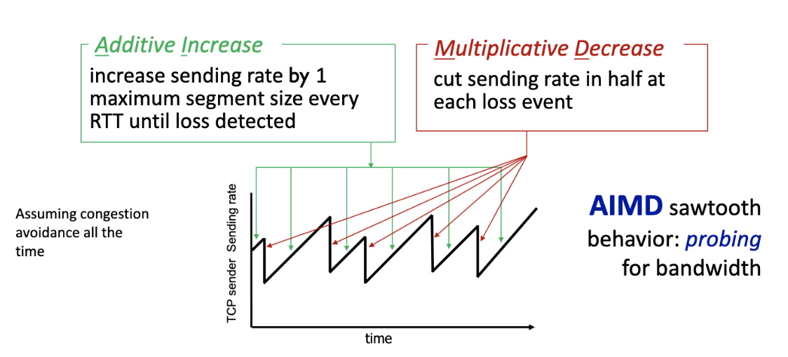
- Saw-tooth behaviour
- indication to back off: A loss!
- By controlling window size, we control the rate!
"Classic" TCP congestion control
- Two “phases”
- Slow Start
- Congestion Avoidance
- important parameters:
cwndssthresh: defines threshold between a slow start phase and a congestion avoidance phase
TCP: slow start (SS)
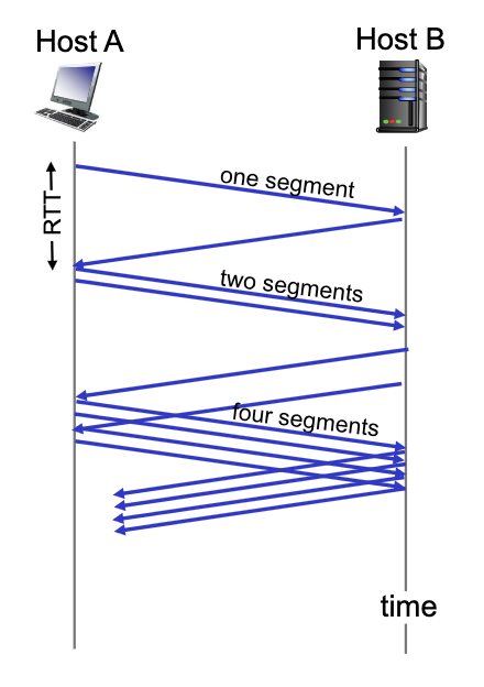
- TCP starts in Slow Start with
cwnd = 1segment and increases the window size as ACK’s are received - During Slow Start, TCP increases the window fast (typically by one segment for every ACK that is received)
- When
cwnd = ssthresh, TCP goes to Congestion Avoidance phase!
Note
Typically, during slow start
cwnddoubles every round trip time: exponential increase (assuming each segment is acked!)
TCP: from slow start to congestion avoidance
When should go from SS to Congestion Avoidance?
When
cwndgets to ssthresh.
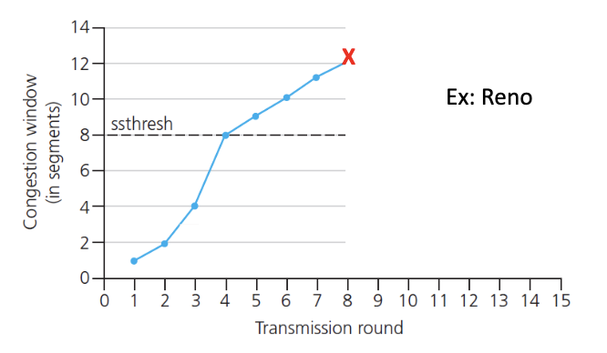
Implementation:
- variable
ssthresh - When we get a loss (on loss event): set threshold to 1/2 of latest value of
cwnd. and decreasecwnd.- Basically update the parameters
TCP: Congestion Avoidance
- TCP is most of the time in this mode
- During congestion avoidance, TCP increase the window (i.e.,
cwnd) slower - How? Depends on the version of TCP
- One segment per RTT (linear increase)
- In Tahoe and Reno,
cwndis increased by one segment every RTT (i.e., for every window of ACKs that the transmitter expects to receive): Linear increase
- In Tahoe and Reno,
- TCP continues to increase
cwnduntil congestion occurs
Congestion detection and reaction to congestion
- Two congestion indication mechanism (i.e., 2 types of loss events)
- 3 duplicate ACK’s could be due to temporary congestion
- Timeout: not enough ACK received likely due to significant congestion
- Basic idea: when congestion occurs → loss: we decrease window size (depends on loss event)
- How much? Depends on the loss event
- TCP Reno - one example of the implementation
- If Timeout happens,
ssthresh = cwnd/2, and setcwnd = 1, and go to the Slow Start phase - If 3 duplicate ACKs occur
cwnd = ssthresh = cwnd/2and stays in the phase. This is called Fast recovery (In Tahoe, sender goes back to Slow Start)
- If Timeout happens,
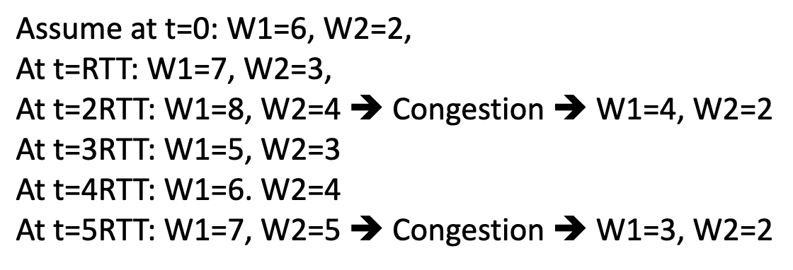
Example: "Classic" TCP congestion control: AIMD
TCP AIMD: more
Why AIMD?
- AIMD - a distributed, asynchronous algorithm - has been shown to
- optimize congested flow rates network wide!
- have desirable stability properties
Why 2 way handshake in TCP would not work?
- server forgets about the client, when the client tries to retransmit, but the server would think its a new
congestion control→ TCP
compute internally the congestion window, which is the w = min(cwnd, receive window(flow control))
slow start, congestion avoidance
2 main char of TCP:
- decide base on losses → indication of congestion is losses (event are loss based)
- 3 losses
- timeout → major event
- AIMD (Additive Increase Multiplicative Decrease)
- Is additive increase a great idea??
Not a a good idea that it is based on losses:
- when losses occur → already too late
- wireless can cause losses!
- punished twice because tcp would think that it’s a congestion → back off
- bad bit/rate
TCP CUBIC
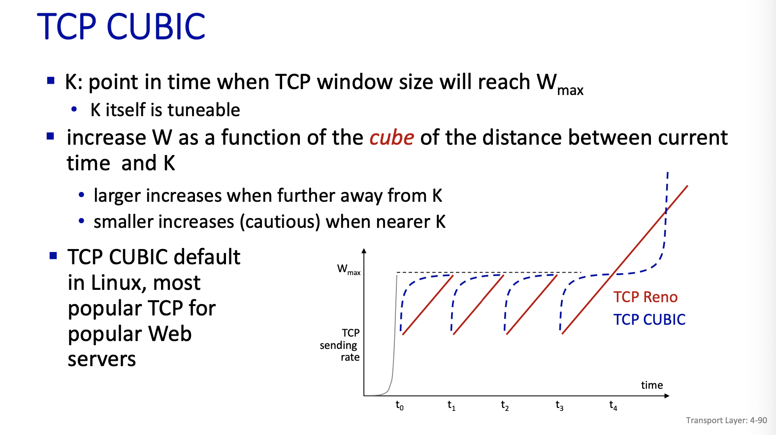
First successful attempt: TCP CUBIC
- we increase faster at the beginning and get more careful when we get closed to . don’t use linear increase.
- : sending rate at which congestion loss was detected
- after cutting rate/window in half on loss, initially ramp to faster, but then approach more slowly

Google came up with detecting congestion based on delay. They created TCP BBR (unfair to others, it just grabs more)
- Idea is do the measurement of RTT (assume path is stable that is if your routing is relatively stable)
- Minimum RTT give an idea of the rate in the base case. Then measure current RTT.
TCP and congested “bottleneck link”
- TCP (classic, CUBIC) increases TCP’s sending rate until packet loss occurs at some router’s output: the bottleneck link
- understanding congestion: useful to focus on congested bottleneck link
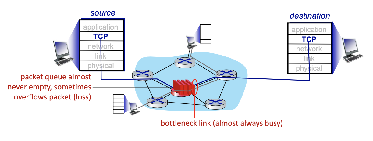
Goal: “keep the end-end pipe just full, but not fuller”

Delay-based TCP congestion control
Keeping sender-to-receiver pipe “just full enough, but no fuller”: keep bottleneck link busy transmitting, but avoid high delays/buffering

Delay-based approach:
- minimum observed RTT (uncongested path)
- uncongested throughput with congestion window
cwndis cwnd/ - congestion control without inducing/forcing loss
- maximizing throughput (“keeping the just pipe ful…”) while keeping delay low (”… but not fuller”)
- a number of deployed TCPs take a delay-based approach
- TCP BBR (“Bottleneck Bandwidth and Round-trip propagation time“) deployed on Google’s (internal) backbone network
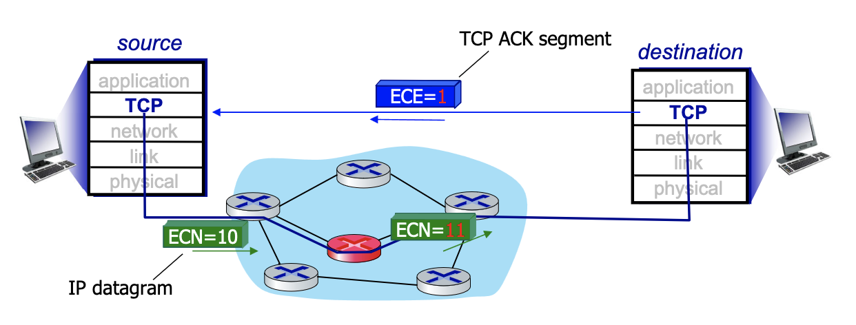
Explicit congestion notification (ECN)
- Another way to detect congestion
- Operator (think Rogers) decides if they use ECN → network assisted
- Mark IP header →IP datagram with 2 bits when there is a problem (router don’t know anything about the TCP). But still putting 2 bits, mark all packets 11 if there is a problem. Which is going to TCP layer of destination. And destination is put the bit on ACK segment (layer 4 TCP) to say there’s explicit congestion, to notify sender of congestion (the E bit)
- involves both IP (IP header ECN bit marking) and TCP (TCP header C, E bit marking)
TCP fairness
Fairness goal: if K TCP sessions share same bottleneck link of bandwidth R, each should have average rate of R/K
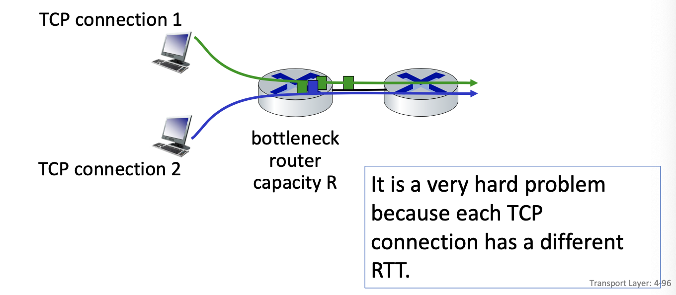
Is TCP Fair?
Example: two competing TCP sessions with same RTT on bottleneck link of rate 10 segments per RTT.
- If we send less than 10 segments we good, otherwise we backoff
- Whole point is to get to a window size that is equal between the two
- Fair is R/K = same rate?
Is TCP fair? A: Yes under idealized assumptions: same RTT fixed number of sessions only in congestion avoidance
