Packet-Switching
Packet-switching
A method of data transmission in which data is broken into smaller units called packets, and these packets are transmitted independently over a network. Each packet is routed through the network based on the destination address it carries, and they may travel via different paths to reach the same destination. Once all the packets arrive at the destination, they are reassembled into the original data.
host sending function:
- takes application message
- breaks into smaller chunks, known as packets, of length L bits
- transmits packet into access network at transmission rate R
- link transmission rate, aka link capacity

Example:
- L = 1500 Bytes = 12,000 bits
- R = 100 Mbps 100 000 000 bps
- one-hop transmission delay = 0.00012 sec = 0.12 msec
Packet transmission delay
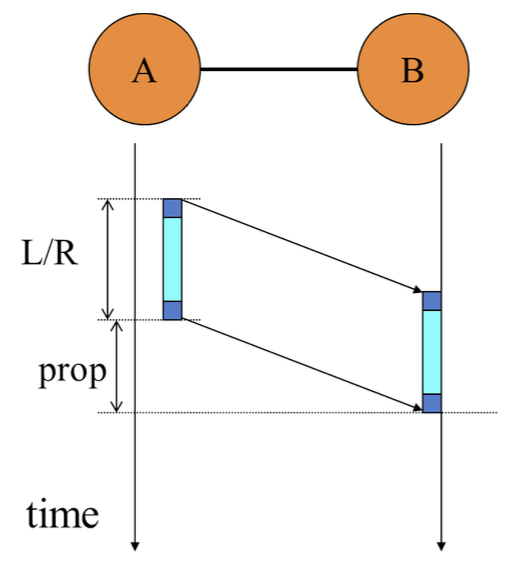
takes L/R seconds to transmit (push out) L-bit packet into link at R bps.
Propagation delay
Takes L/R+prop seconds (prop = propagation delay) for the packet to fully arrive at the receiver.
Transmission delay:
Impact of propagation delay:
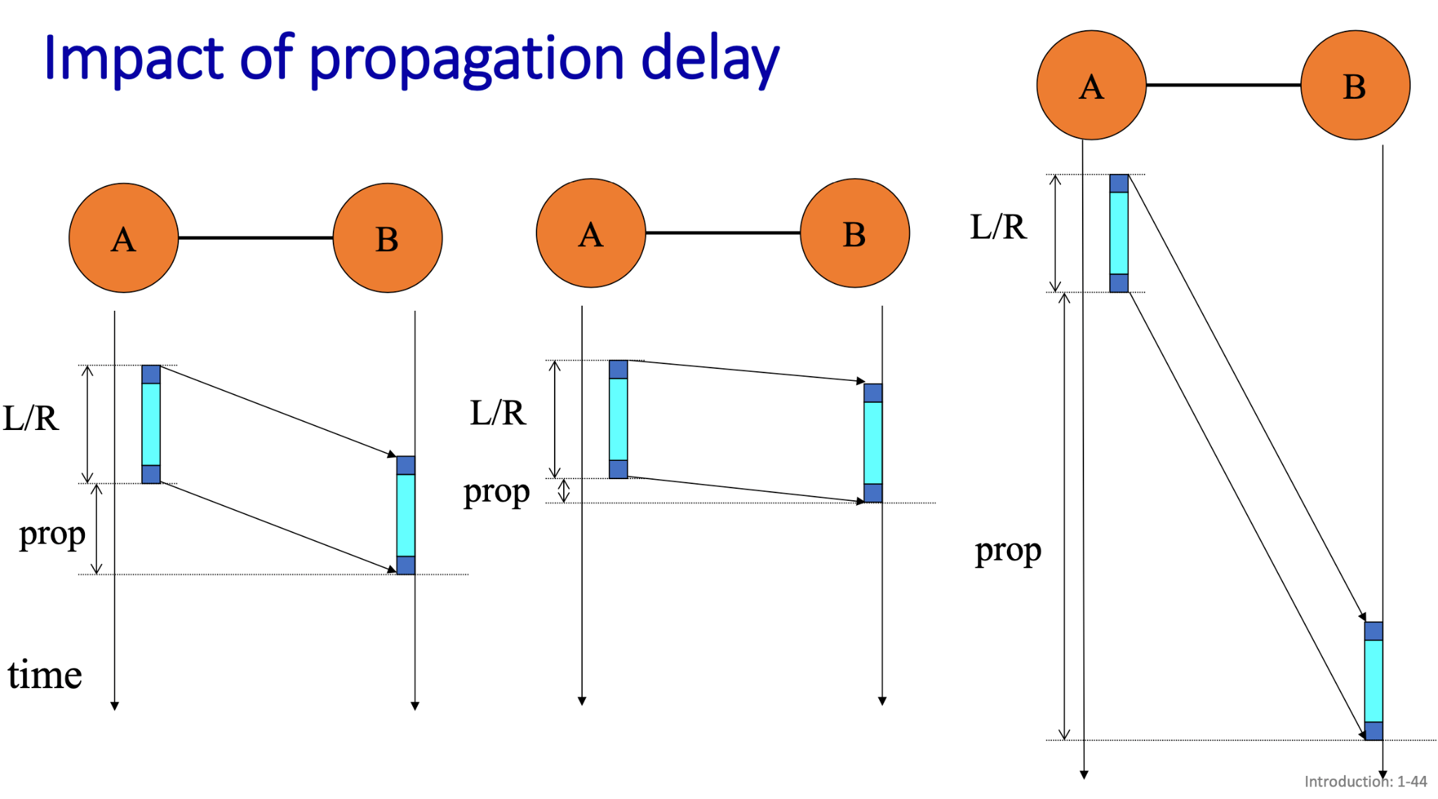
- First diagram:
- This diagram shows the scenario where both transmission delay (L/R) and propagation delay (prop) are present. The first packet is being transmitted from A to B, and part of it has already been transmitted onto the link while the rest is still being transmitted.
- The slanted lines show the point in time when the packet has fully been sent from A but is still traveling through the medium (affected by propagation delay).
- The total time for the packet to arrive at B is the sum of the transmission delay L/RL/R and the propagation delay prop.
- Second diagram:
- The transmission delay remains the same, but the propagation delay causes the packet to take longer to fully arrive at B after being transmitted.
- Third diagram:
- This diagram appears to focus heavily on the propagation delay, showing that the propagation time prop is a major factor in the total delay.
- Shows how, even after the entire packet has been transmitted (after L/RL/R), the propagation delay significantly adds to the total time before the packet reaches B.
Store-and-forward
Entire packet must arrive at router before it can be transmitted on next link.
The pipelining effect
Packets shouldn’t be too big, better break up a big file into small ones.
breaking a large file into smaller packets allows for pipelining, where multiple packets can be in transit across the network at the same time.
Buffer and queueing
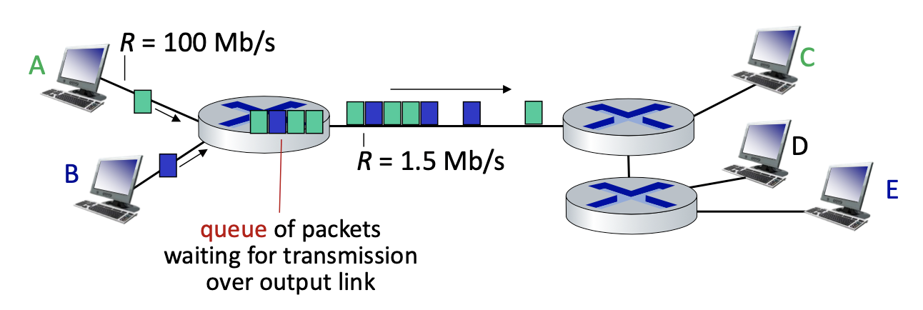
- Packets share resources (buffers, links) without reservation
- The packet to be transmitted next receives full rate
- Queueing occurs when work arrives faster than it can be serviced
Packet queuing and loss:
If arrival rate (in bps) to link exceeds transmission rate (bps) of link for some period of time:
- packets will queue, waiting to be transmitted on output link
- packets can be dropped (lost) if buffer in router fills up
Packet-switching vs. Circuit-Switching
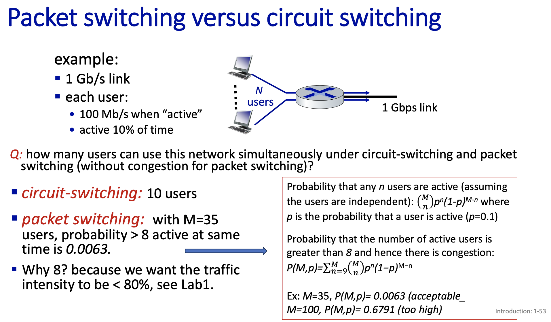
- Unlike packet switching, where data is divided into packets and dynamically routed through the network without dedicated resources, circuit switching requires a dedicated path to be set up before data can be transmitted. This leads to lower efficiency and flexibility but ensures consistent performance.
In contrast:
- Packet switching is more efficient and flexible, as packets from multiple users share the same network resources dynamically, and there’s no need to reserve resources ahead of time. However, this can lead to variable performance because packets might experience delays or congestion in the network.
Packet delay
- packets queue in router buffers, waiting for turn for transmission
- queue length grows when arrival rate to link (temporarily) exceeds output link capacity
- packet loss occurs when buffer to hold queued packets fills up
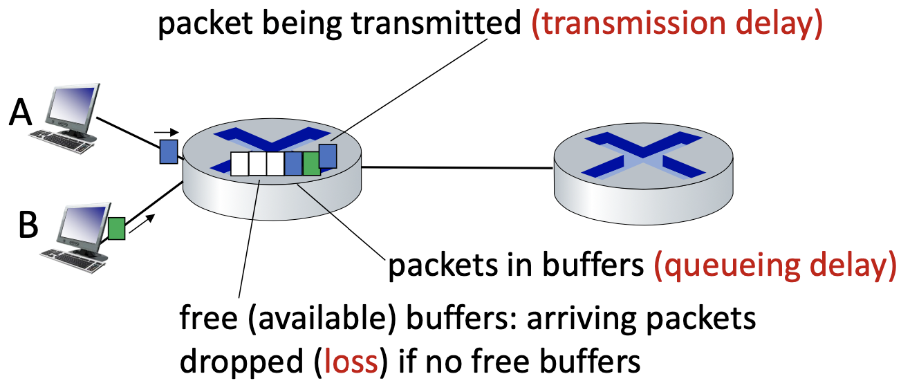
4 types of delay:
- Processing delay
- Queueing delay
- Transmission delay
- Propagation delay
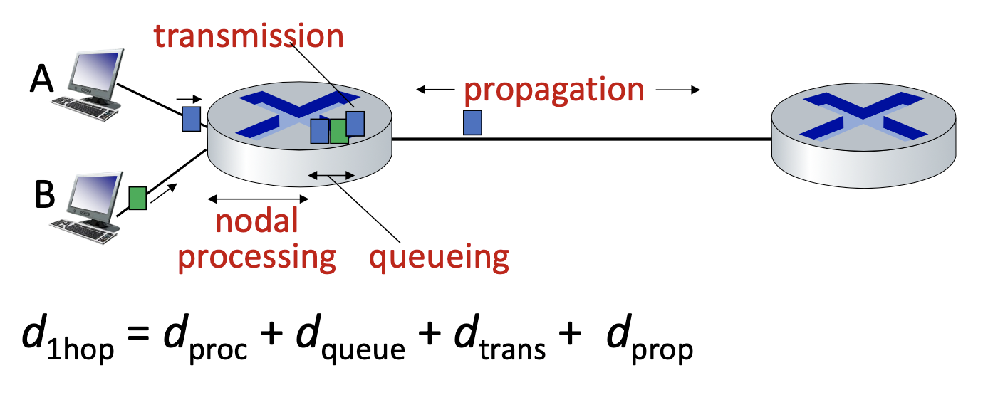
- nodal processing
- check bit errors
- determine output link
- typically < microsecs
- queueing delay
- time waiting at output link for transmission
- depends on congestion level of buffer
- transmission delay
- packet length (bits)
- link transmission rate (bps)
- propagation delay
- length of physical link
- propagation speed ()
and very different!!
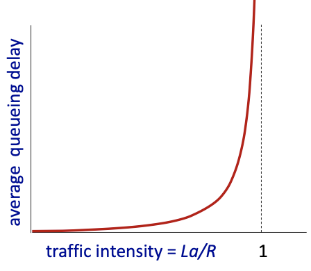
Packet queueing delay
- average packet arrival rate
- packet length (bits)
= arrival rate of bits / service rate of bits = “traffic intensity”
- : average queueing delay small
- average queuing delay large
- : more “work” arriving is more than can be serviced - average delay infinite!
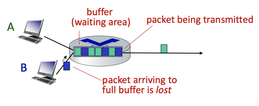
Packet loss
- queue (buffer) has finite capacity
- packet arriving to full queue are dropped (lost)
- lost packet may be retransmitted by previous node, by source end system, or not at all!
Throughput
Throughput
Rate (bits/time unit) at which bits are being sent from sender to receiver
- instantaneous: rate at given point in time
- average: rate over longer period of time
diagram shows a simple analogy with fluid flowing through pipes, where data (bits) is compared to
Factors influencing throughput:
- Transmission Rates:
- The transmission rate of the server (the rate at which bits are sent into the network).
- The capacity of the communication link (the rate at which bits can be transmitted across the link).
The throughput will depend on the minimum of (the rate the server can send data) and (the rate the link can carry data).
Bottlenecks in throughput:
- Scenario 1: :
- If the server’s sending rate () is slower than the capacity of the link (), the overall throughput is limited by the server’s sending rate. The maximum throughput will be bits per second.

- If the server’s sending rate () is slower than the capacity of the link (), the overall throughput is limited by the server’s sending rate. The maximum throughput will be bits per second.
- Scenario 2: :
- If the link’s capacity () is slower than the server’s sending rate, the link becomes the bottleneck, and the throughput is limited by the link capacity. The maximum throughput will be bits per second.

- If the link’s capacity () is slower than the server’s sending rate, the link becomes the bottleneck, and the throughput is limited by the link capacity. The maximum throughput will be bits per second.
Throughput network scenario:
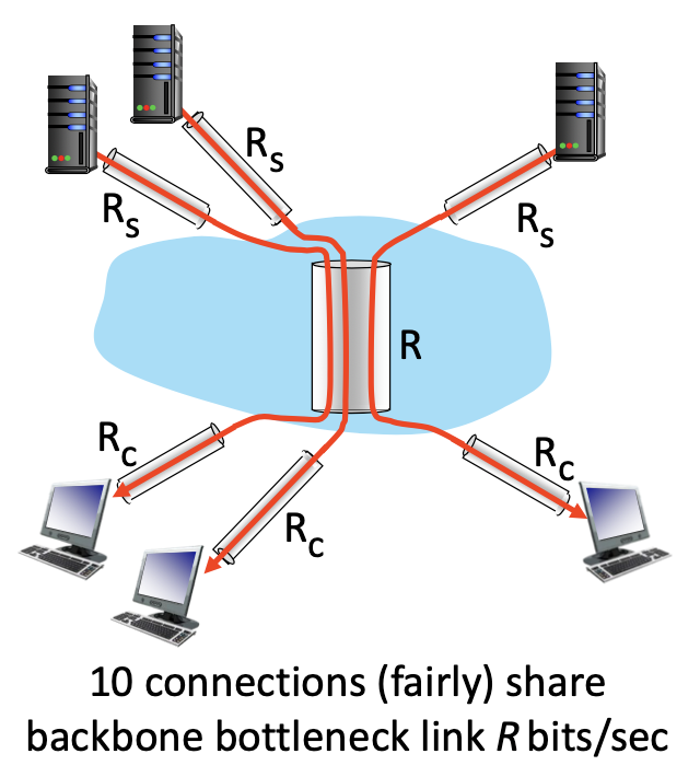
- In a network with multiple connections sharing a common link (such as a backbone network), the throughput per connection is determined by the minimum capacity of the links involved.
The formula:

- Here is the capacity of the client’s link, is the server’s sending rate, and is the share of the backbone’s capacity that each of the 10 connections receives.
In practice, either the client link or the server link is often the bottleneck, limiting the throughput.

