Chapter 5 - ECE222
Hierarchy of Memory
- Registers (closest to CPU)
- fastest and smallest
- Cache
- called “cache bloc” or “cache line”
- L1, L2 and L3 caches. L1 is smallest and closest to the CPU
- Main Memory
- HDD
- slowest and largest
Locality
- Temporal Locality:
- Spatial Locality:
Using memory:
- When the CPU tries looking for data in the cache, if it finds it, it is called a hit. Otherwise, it is a miss, which means it has to look elsewhere (higher levels of cache (which is Level1)).
- Hit time is the time required to access data in the upper level, including time to determine if it’s a hit or a miss.
- dRAM is a lot slower than sRAM since it is on another chip, so it takes a lot of time for data to be transfered
- cache is about 100x faster than main memory, which is about 1 million times faster than HDD (secondary memory)
Data is stored in two levels.
Definitions:
- hit rate: fraction of memory accesses found in upper level.
- miss rate: 1 - hit rate, fraction of memory accesses not found in the upper level.
- hit time: time to access data in upper level (including time to determine that it is a hit or a miss).
- miss penalty: time to replace a block in the upper level with a block from lower level, plus time to deliver block to processor.
Cache
3 kinds of cache:
- Direct mapped
- Fully associative
- N-way set associative
→ problem: cache is small amount of memory, while our main memory is huge. How do we decide which items can go on the cache, how do they go on the cache? Where do they go on the cache?
Direct mapped cache:
Definition: direct-mapped cache A cache structure in which each memory location is mapped to exactly one location in the cache.
Tag The tag needs just to contain the upper portion of the address
Valid bit Add valid bit to indicate whether an entry contains a valid address
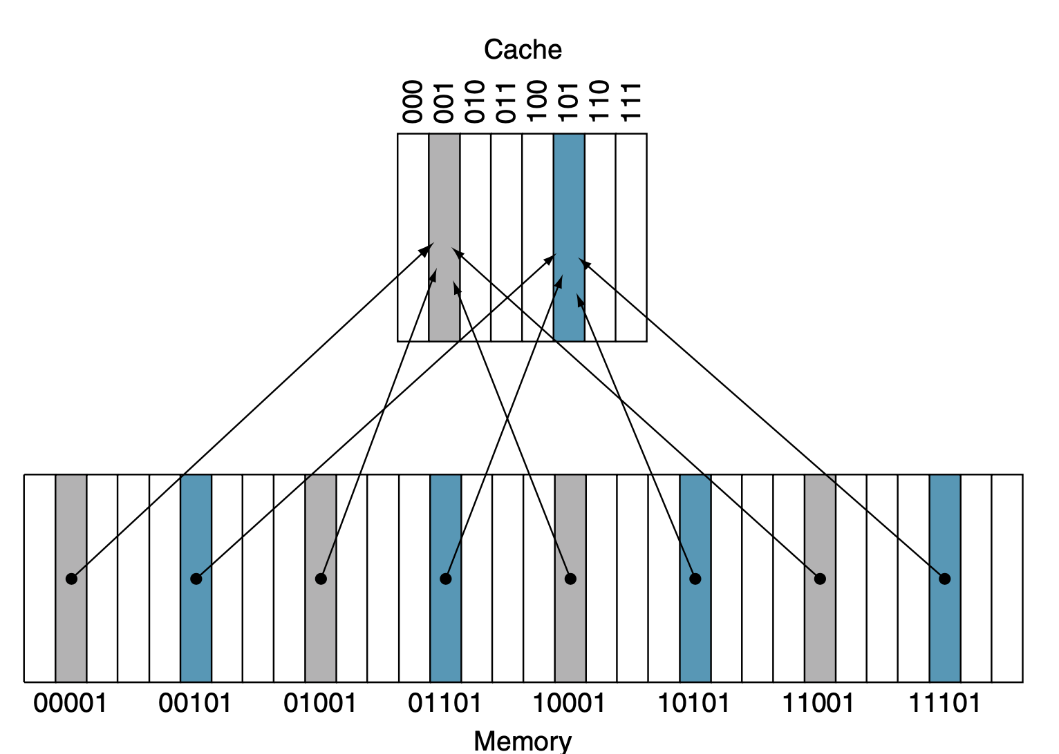
We have word addressable memory (16 words in our main memory and 4 words in our cache). This mean that we will need 4-bit addresses (as we have 16 words in the memory, 4 bytes/ word, 4 words).
We can use direct mapped cache:
-
Each word in the cache will have a valid bit, a tag and a cache block (=1 Word).
-
The address in the cache will correspond to the LSBs of the main memory (ex: right most).
- In our example, as cache addresses have 2 bits, the address of the cache maps with the 2 LSBs in an address of the main memory. So, address 00 in our cache will map to any address in the main memory which has LSBs 00 (which could be 0000, 0100, 1000, 1100).
-
We then set the tag for a word in memory in the cache to the rest of the address of the main memory word which it refers to. This, combined with the valid bit (0 or 1), says if when looking for some data, we get a ‘hit’ or a ‘miss’.
-
If we want to load a word at main memory address 0b0110, we would have to load the word into cache register 10, put the rest of the main memory’s target address into the tag (which would be 01), and then set the valid bit to 1.
-
Valid bits are set to 0, when the processor powers up, or in some implementations when you switch from one process to another so that old datat gets wiped out.
Write Performance
 direct-mapped cache example: If we want to write to it, we first need to wait a cycle to get the hit, then we can write to it on the next clock cycle.
Direct Mapped Cache Example:
-
Given:
- 2 words / block
- byte-addressable memory
- 16 blocks in cache
-
How does an address (a line of info to look for some data in the cache, which would be stored in 32 bits in RV32I or 64 bits in RV64I) look?
- 2 bits for the Byte offset
- 1 bit for the block offset
- 4 bits for the cache index (since we have 16 = 2^4 blocks in the cache)
- done first
- n bits for the tag base don the size of main memory
-
How do we use the address?:
- we first take the cache index and check the cache block referring to it.
- we then check the valid bit for 1. If it is a 0, we have a miss. If it is a 1, we need to check the tag.
- we check if the tag equals what is in cache to make sure it is the same address from the main memory which we are looking for (since each cache block can be for a whole bunch of different addresses in the main memory).
- we then use the block offset to see which of the two words we want (as we are given that there are 2 words per cache block in the example). If it was 1 word per cache block, then this step can be skipped.
- we then check the byte offset to see which byte we want from the word (for stuff like lb)
- If it is 00, we might get the whole word or just the first byte (based on other control logic, which will be determined based off if we have like a lb instruction or something that needs the whole word). If it is something like 11, then we just get the last byte.
- If it is a miss, then it has to check in the main memory.
-
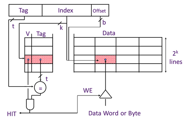
Accessing data from the cache:
- We compile the tag, index, block offset (BO) and the byte offset (bo) and try accessing it from the cache.
- Simultaneously we:
- check if we have a ‘hit’: at the cache block chosen by the index, we check if the valid bit is a 1, and compare the tags.
- If there is no ‘hit’, then we must check the next segment of memory.
- Use BO (block offset) to get the correct word (using a 2-1 mux), and also use the byte offset (not show on the diagram) to apply some byte offset if required.
- check if we have a ‘hit’: at the cache block chosen by the index, we check if the valid bit is a 1, and compare the tags.
How to calculate total # of bits in the cache? Assume:
- RV64i
- direct mapped cache
- block i cache
- words block size calculate total # of bits in the cache:
- Byte offset: 2-bits
- Block offset: m-bits
- Index: n-bits
- Since it is RV64i and addresses are 64-bit long, the tag will be 64-n-m bits = 62-m-n
Fully Associative: Another kind of cache
A cache structure where a block can be placed in any location in the cache. It is called Fully associative, because a block in a memory may be associated with any entry in the cache. We will have to search every entries in the cache, because a block can be placed in any one of them.
- Each block of cache has a valid bit, a tag, a block offset and a byte offset.
- The index field is basically absorbed into the tag field.
- When we want to access data, we check EVERY single row and compare the tags (and check for valid bits). If we find a matching tag (and a valid bit is represented by 1), then we have a ‘hit’. If we cannot find a matching tag with valid bit 1, then we have a ‘miss’.
- Pro: there aren’t really conflict mapping issues like from direct mapped cache. We can store data wherever we want.
- Con: Very inneficient hardware wise, cost a lot. Because you have to compare every tag at once, but that needs a ton of comparison units.
Set Associative: In between direct mapped and fully associative
A cache that has a fixed number of locations (at least two) where each blocks can be placed. From the textbook: apparently fully associative is a particular type of set associative (one way set associative).
- n-way set associative
- Basically take index of our cache, but for each index we can store more than one block. In fact, we can store blocks (remember that a block can be some power of 2 words of memory).
- This design combines the benefits of the 2 prior cache designs. We can use the index to quickly narrow down the cache to just rows (with an n-bit index), and then we compare the tag with each of those rows (and valid bits) to see if the block of memory we want is actually in the cache.
- We can figure out if it is a hit or not in just 1 clock cycle! This design is often used for L1 cache since it needs lots of circuitry but is very fast.
- We have a miss penalty of course, which is the time it takes to try again at the next level cache. For instance, if we are at the L1 cache and miss, the miss penalty is the time to go to L2 cache. L2 cache’s miss penalty is the time to go to L3 cache when it misses, etc.
- Penalties/timers for this cache stuff (presumably all the different caches we learned about) are all multiples of clock cycles.
- For example: a hit can be just a clock cycle, or the time it takes for us to look and get a miss and suffer the miss penalty will just be a multiple of a clock cycle.
- Each block has its own valid bit and tag (and block)
What we should understand for all 3 cache designs
- Where to place the block / cache line
- How the block is found
- Which block to replace
- for direct mapped cache there is only 1 block you can replace since things map directly
- for n-way set associative, we can replace any block which matches the index (there will be n of them)
- What happens on a write (didn’t get to that lesson yet)
What happens when we write data
- On a miss, we can either:
- write allocate: which means to write the block into the cache.
- It could be fetched from somewhere like L2 memory, or maybe main memory?
- when we have write allocate, we cn also have a [write back]: when the block is evicted from memory, (miss on the read or write of data in the cache).
- write non-allocate (no write allocate): don’t bring it into the cache. We must then write the block to the write buffer, which will write it to main memory.
- write allocate: which means to write the block into the cache.
- On a hit: If the data is already in the cache, we have the choice for if we write to the main memory or not. We can either:
- write back (write to cache only)
- This data will only be written back to the main memory when this block is evicted (since it has a dirty bit set to 1: means that we changed it already).
- The main cost of write back is that it requires another bit for the dirty bit.
- write through (write to write buffer which writes to main memory): write to both cache & memory
- Generally higher traffic but simpler pipeline & cache design.
- Write through would put a higher strain on the write buffer compared to write back.
- write back (write to cache only)
- Write buffer: writing to the main memory is very slow so we don’t want to wait for that. The write buffer comes in. Write buffer writes to the main memory in its own time.
- When we write to main memory, we usually use write-buffer since writing to main memory takes dozens of clock cyles apparently.
- We can use a [dirty bit], which says that this data has been modified without being written to the main memory yet. If this block is overwritten, we must write to the main memory first. This bit should be set whenever we write to the cache but not also to the main memory (the hardware will have to support it of course).
- These will be bits stored in the cache.
Reducing Write Hit Time
Problem: Writes take two cycles in memory stage, one cycle for tag check plus one cycle for data write if there is a hit. Solutions:
- Design data RAM that can perform read and write in one cycle.
- Pipelined writes: Hold write data for store in single buffer ahead of cache, write cache data dring next store’s tag check.
Equations
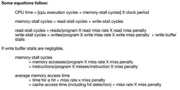
- Need to especially know about [memory-stall], [read-stall] and [write-stall] cycles equations. But I think all of these are required.
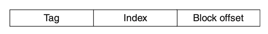 Remember:
Index: used to find the set containing the address of interest
Tag: used to find the block within that set
Block offset:
Remember:
Index: used to find the set containing the address of interest
Tag: used to find the block within that set
Block offset:
Examples
Most processors have 2 levels of cache. If a miss occurs to the first level cache (closest to processor) and if the data is available in the seocnd level cache, then the miss penalty of the first level cache will essentially be the access time of the second-level cache. If neither cache have the data, the miss penalty will be larger and main memory data access will be required.
Example:
Calculate the performance improvement for a two level cache implementation compared to a one-levl cache implementation where: a) processor has base CPI of 1 and clock rate 4GHz b) main memory access time of 100 ns (including all the miss handling) c) assume miss rate per instruction at primary cache is 2% d) secondary cache is assumed to have 5 ns access time (for hit or miss) with miss rate to main memory of 0.5%
Case 1 (one-level cache): {L1, MM}
-
- The 400 is given to use as the time to go to the next level of memory (main memory; 100ns) * cycles/time = clock rate.
- Result is 9
Case 2 (two-level cache): {L1, L2, MM}
- = 1 + 0.02(20 + 0.005 * 400)
- 0.005 * 400 is the main memory access time
-
- The prof said that the 0.5% miss rate for level 2 is a fraction of all cache accesses, not just the ones that make it to level 2.
Question: Determine if each address is a hit or a miss. Assume Direct Mapped Cache, 8KB (), 4 words/block cold start.
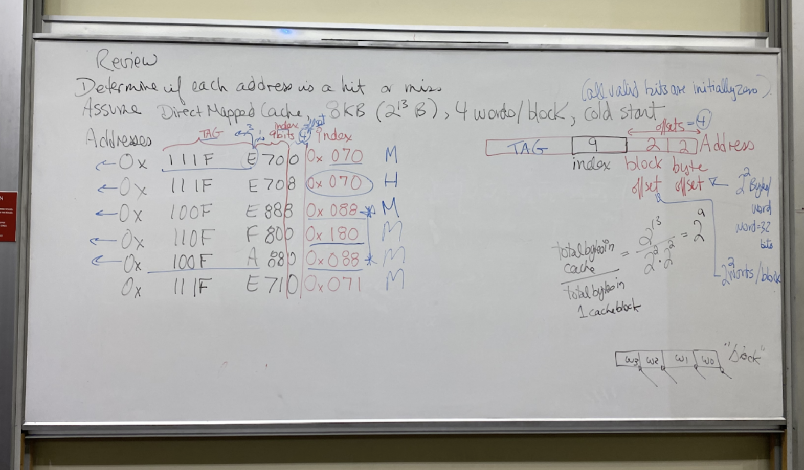 Addresses:
0x 111F E700
0x 111F E708
0x 100F E888
0x 110F F800
0x 100F A880
0x 111F E710
Addresses:
0x 111F E700
0x 111F E708
0x 100F E888
0x 110F F800
0x 100F A880
0x 111F E710
- Solution Prt1; understand what the address does:
- Cold start means that everything starts at 0.
- random note: we often will only initialize the valid bit to a 0 since it might be more difficult to do everyhting else (tag, etc) as 0.
- Review of a hit: we do load instruction and the value was already in the cache, so we don’t have to go to the main memory for it.
- We start with determining what the address means.
- Our byte offset will be 2 bits. Since the question states “4 [words] per block”, we will be working with words, which have bytes. If the question had said “2 [double words] per block”, since each double word has bytes, we would want the byte offset to be 3 bits.
- Our block offset is 2 since we have words / block.
- Index:
- Since it is a direct-mapped cache, we only have 1 block per row of the cache.
- Since our cache has bytes, and we have bytes/word and words/block, we have . This means our index section needs to have 9 bits to select from the
- The rest of the address is the tag, which stores the remainder of the address.
- Solution part 2; check if we have hits or not:
- For each of the above given addresses, the first (Least Significant) hex digit will make up the block and byte offset, so we can ignore them.
- Then, the next 9 bits (2 hex digits + 1 bit) make up the [index]. They will be the following:
- 0x070
- 0x070
- 0x080
- 0x180
- 0x088
- 0x071
- The [tag] will be the rest of it.
- 0001 0001 0001 1111 111
- 0001 0001 0001 1111 111
- 0001 0000 0000 1111 111
- …
- The first load will miss, since we are beginning on a cold start.
- It will then store the tag at the appropriate cache block. So, at the cache with index 0x070, it will set the valid bit to 1, and the cache row’s tag to “0x088FF”.
- If we later get another address that has the same index but different tag, it will be a miss.
- It will then store the tag at the appropriate cache block. So, at the cache with index 0x070, it will set the valid bit to 1, and the cache row’s tag to “0x088FF”.
- The second address has the same index (0x070) as the first address and the same tag, so it will be a hit. Valid bit remains 1 for that cache row.
- The third address will be a miss, since it has a new index not seen before yet since the cold start.
- We will then, at index 0x088, store the tag into the cache at that row. We will also set the valid bit to 1.
- The fourth address has an address not seen before, so it will once again be a miss. It will store the tag at the cache row for index 0x180. It will set the valid bit for that row to 1.
- The fifth address matches an index from before, but the tag differes, so it is a miss. Valid bit remains a 1.
- The sixth is a miss since the index was not used before. We will set the valid bit to a 1, and put the tag into the row of the cache.\
Example:
Question: How many times improvment in performance does a ‘perfect’ cache that never misses have over a real cache?
- Assume:
- 2% icache (instruction cache) miss rate
- 4% dcache (data memory cache) miss rate
- Base CPI with no memory stalls is 2
- Miss penalty is 100 cycles
- Frequency of all loads/stores is 36%
First, we will calculate the additional cycles cost in a non-perfect cache:
- number of cycles penalty from icache misses:
- This is because we must access instruction cache for every instruction. 2% of the time, we will have a 100 cycle penalty.
- number of cycles penalty from dcache misses:
- 36% of the time we accesses the dcache, which has a 4% chance for a 100 cycle penalty.
- Remember that we accesses the dcache ⇐> we do a load/store.
Now, we can see the CPI for a non-perfect cache with the above stats:
- Total cycles from imperfect cache:
Cacluating Times Improvment (the answer):
- The improvment of X from Y is Y/X.
- The improvement
- Alternate:
- The prof said that the “real cache performance = 5.44 * I * clockperiod and “perfect cache performance = 2 * I * clockperiod”. I reverse to “total number of instructions”. The result is equivalent: 2.72 time improvement.
What stuff must we be able to do for Ch5 for the content so far?
- Given a cache: be able to determine what kind of hardware it is, and see if the data you want is in the cache.
- Know the 3 different kinds of caches
- If we are given cache contents and given an address and told what kind of cache it is, determin miss, or hit & what the data is.
- Be able to do the math kind of questions like the one above.
- For any cache, given the details, determine the field sizes for the address within the cache.
New More-Realistic Pipelined Processor:
- One thing we are missing right now is being able to do multiple processes at once.
- Solution:
- We will use a virtual address space.
- The virtual addresses will map to real addresses in the physical main memory.
- The virtual address space can be up to bytes for RV64I, even though the real memory may not support that. We will just be mapping the regions which are actually used to the physical main memory.
- We will divide the main memory into “Pages”, and the virtual memory into “Pages”, and will map pages in the virtual memory to pages in the real physical memory.
- The virtual addresses between different processes may collide, but not the pages in physical memory.
- We can have global libraries in the physical memory which can be used by both.
Notes on Pages:
- Pages are fixed sizes.
- For example: 4KB.
- Our HDD can store process pages which are typical active. When we need data from a page which is not in main memory, we will bring them into the main memory.
- The main memory has basically enumerated page slots which can store pages from HDD.
- Data from these pages now in the main memory can be brought into the cache into cache blocks/lines.
- Kinds of misses:
- If we want to access data in the cache but it is not there, it is a cache miss.
- If we want to access data in the main memory from a page which is not there, we have a page fault.
- What happens if we miss:
- For a cache misses: We will have to have some block replacement algorithm, such as least recently used. We will then need to turn on the set bit.
- For page faults: We will use an LRU policy, and also set the valid bit.
- This means wwe will displace a page slot with the page we want via LRU.
- **Where the data goes (where it is placed in the storage medium): **
- Between cache and main memory: direct-mapped, fully associative, n-way set associative.
- Between main memory and HDD: fully associative
- How do we write (on a hit or a miss):
- Between cache and main memory: Write-through, write-back.
- Between main memory and HDD: Write-back.
- Always write back since getting data from the HDD is very slow.
- I guess this means that we will always make use of a dirty bit for our pages, as we will never want to update main memory & HDD simultaneously, and instead would prefer to just write to main memory, and then write to HDD only whent he page is evicted and the dirty bit is on.
- Always write back since getting data from the HDD is very slow.
- How Addresses work:
- Between cache and main memory: physical addresses.
- Between main memory and HDD: virtual → physical address.
- Uses a page table.
- Set by OS so there are no collisions between pages in the main memory.
Review (active recall ask yourself)
- Do we need virtual memory if we only have 1 process?
- No, virtual memory is useful for more than 1 process.
- What are the benefits of using a virtual memory?
- To help partitioning the memory to be used across different processes.
- Allows to have multiple proccesses using the memory at the same time, via the usage of pages.
- Security benefits.
- Can support up to bytes of virtual memory, which will be mapped within the bounds of the physical memory.
- How is virtual memory implemented?
- Transferring data:
- Cache ←> main memory: cache blocks
- Main memory ←> HDD: pages (with fixed sizes; 4 KBi a common example).
- Writing:
- We use the LRU method for both cache misses and page faults.
- We can have pages from the OS, and from some number of other programs in main memory simultaneously.
- Transferring data:
- How is the layout of memory:
- Cache ←> MM: direct-mapped, fully associative, n-way set associative.
- MM ←> HDD: Always fully associative.
- Each page could go in any slot.
Implement Virtual Addresses:
Question:
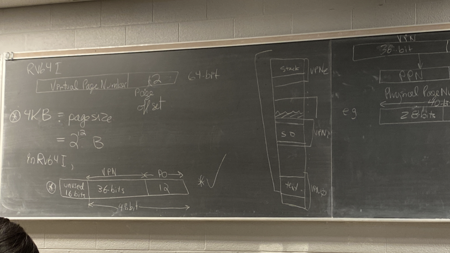
- Assume pages are 4kB (pages are always fixed size).
- RV64I
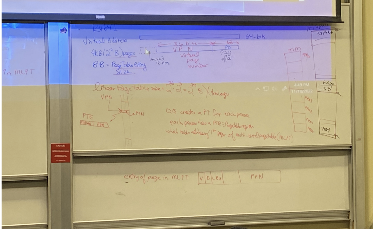
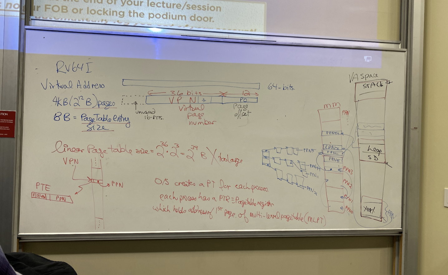
Virtual Address:
- Each page is 4kB == (bytes), so our address will have a 12-bit Page Offset (PO).
- The rest of the address is called the Virtual Page Number (VPN). .
- In reality, this is a massive number of pages. We could use them if we wanted more pages, but it won’t be necessary.
- We will consider the top 16 bits to be unused, so the VPN in our example will only be 36 bits. The prof justified this by claiming it is what is done right now in the industry.
- In the virtual memory, we can fit the virtual pages in it.
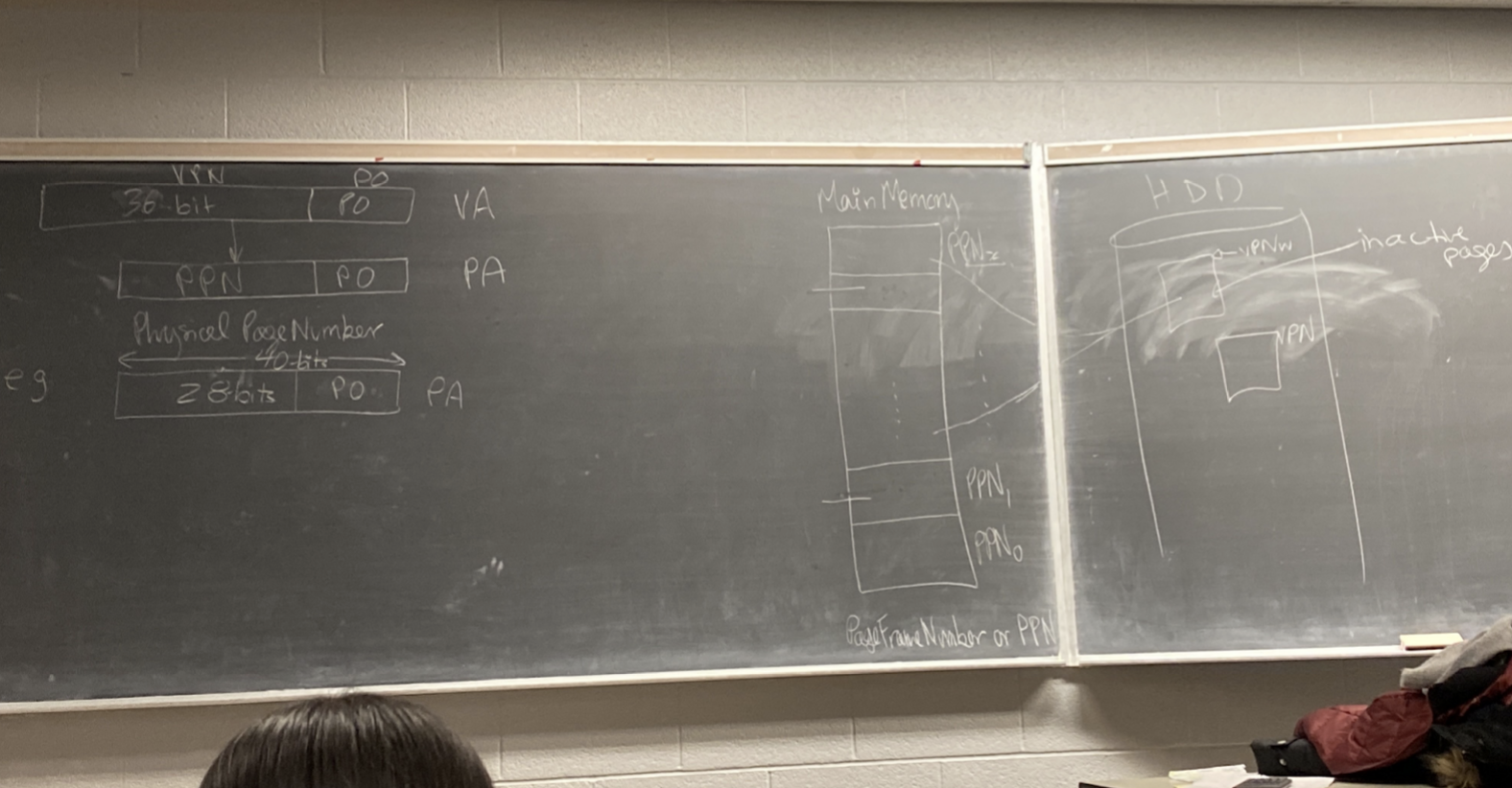
Physical Address:
- The [Physical Address] consists of a 12-bit [Page Offset], and the remaining bits are the [Physical Page Number].
- For example: we will say the physical address only has 40 bits, so 12 bits will go to the Page Offset, and then 28 bits will go to the physical page number.
- There are fixed number of physical pages which can be stored in the main memory, which is determined by hardware size.
Virtual ←> Physical Addresses:
- [Virtual pages] exists in the HDD, where they are inactive. When they are brought into the main memory so that they can be used, they will be translated to use physical addresses, and become a [physical page]. This translation process basically sets up addresses in the page to behave correctly at whichever physical page slot in the main memory they are brought into.
- Page tables (by the OS) will map VPN ⇒ PPN when they are brought into the main memory.
- Pages are either in the HDD and inactive or are active in the MM. If we try accessing data from a page which is not in the MM, we have a page fault and must bring it into the MM.
Problems with making page size larger:
- As pages become larger, it is slower to move them around whenever you have to do it.
How to map VPN to PPN:
- When mapping, the [Page Offset] remains the same. The page offset just points to byte 0 of the data we want in the page.
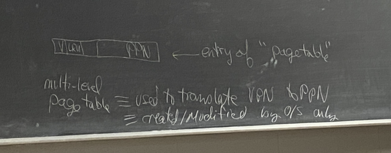
- Page Table:
- Allows us to translate from VPN to PPN.
- Defined by the OS. A random process cannot change data in the page table because then it could access whatever data it wanted which is bad.
- If something else tried to access the page table, it would be an illegal access.
- With the above question, we had had virtual pages. However, the page table also needs to able to be stored within a page, as it is data that will be accessed by the OS.
- We will have it be a [mult-level] page table since we just agreed it would be too large if it included every virtual page.
- The number of levels will be the number of possible virtual pages/size of a page: .
- If our page table is full and we need more space, we will use the LRU replacement policy.
- What data should our page table include?
- Valid bit: so we know if it is MM or not. 1 means it is an active page in MM, 0 means it is not active.
- LRU bits to know if it was recently used or not.
Example:
 Situation:
- RV64I
- virtual address is 64 bits.
- 4kB () pages
- pageTable entry size
How the Virtual address is composed:
- Upper 16-bits are not used (industry standard).
- PO (Page Offset) is 12 bits since we have byte-accessible memory
- The rest (middle 36 bits) is the VPN (Virtual Page Number).
Using the page table:
- Page table entry composition:
- Valid Bit
- If we are looking for a table and it is 0k that means it is not set. This would result in a page fault.
- Dirty Bit
- When evicting a page, if the dirty bit is on, we must write-back to the HDD the data before evicting.
- LRU
- Multiple bits which are used to help us figure out which page should be evicted when we need space.
- PPN
- Valid Bit
- If we had a linear page table, we would have to be able to map pages for all of the physical MM. This would be a massive table. It maps the virtual addresse to the physical addresses(not the other way around).
- The OS is the only one who can write to the page table.
- The size of the linear page table would be: (number of VPNs available in a virtual address) * (size of a page table entry size: given to be 8B = ) == .
- For multi-level page table, the OS creates a PT (Page Table) or each process. Each process has a PTR (Page Table Register) which holds the address of the page of the MLPT (multi-level page table). It is a register in the CPU.
- This (the MLPT) takes up multiple pages of course (just like the linear one would), as it will still need to work for all possible VPNs and thus needs lots of table entries.
- How many bits will we need to access the page in the MLPT (multi-level page table)?
- First, we must calculate
Virtual Machines
abstraction provided by OS to a process
- virtual memory, subset of instructions, most of hardware registers, system calls file I/O etc. A virtual mahine
- Given: complete ISA, physical memory, pagemaps, access to I/O devuces, traps / interupts, no predefined system calls
- This is the abstraction provided to the process.
- more powerful, stronger abstraction, all owned by the OS
- process share the hardware virtual machine
- The OS for this is Virtual Machine monitor - vmm
- a guest OS can be run inside the virtual machine
- run as a user process in user mode
- anything unusual or privilege instructions will trap to the vmm.
Assignments Questions 06/12/22
Read BW B/cycles: bandwith between the Cache and Memory. If read miss, we need to bring in the block. Would also bring a block in on write miss and it’s a write allocate. Those are the two situations when the memory comes from memory to the cache.
Write BW B/cycle: Cache → Memory: word on a write + write through, blovk for a write miss or read miss + D=1 + evicted (implied though) + it is write back.