Control Flow Graphs (CFG)
Control Flow Graphs (CFGs)
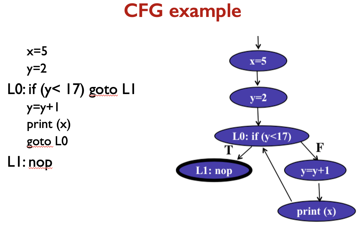
- A CFG models all executions of a method by describing control structures
- Nodes:
- Statements or sequences of statements (basic blocks)
- Edges:
- Transfers of control. an edge (s1, s2) indicates that s1 may be followed by s2 in an execution.
- Basic Block:
- A sequence of statements such that if the first statement is executed, all statements will be (no branches)
- Intermediate:
- Statements in a sequence of statements are not shown, as a simplification, as long as there is not more than one exiting edge and not more than one entering edge.
CFGs are sometimes annotated with extra information: branch predicates, defs, uses.
The if Statement
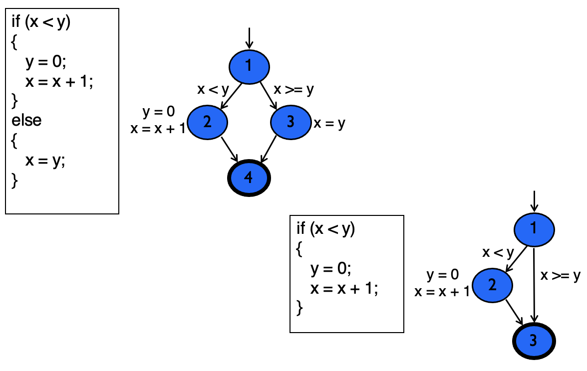
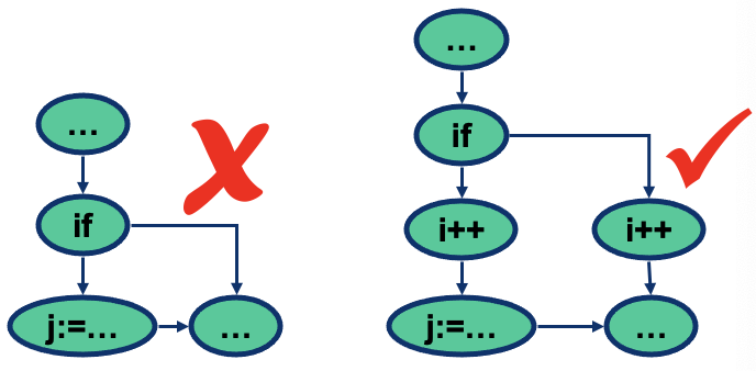
- From source code to control flow graph - issue about branching
- In a control flow graph, nodes corresponding to branching (if, while, …) should not contain any assignments
- This paramount for the identification of data flow information
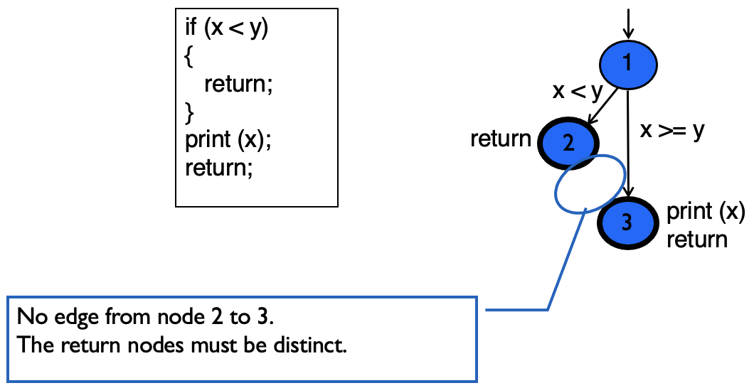
The if-Return Statement
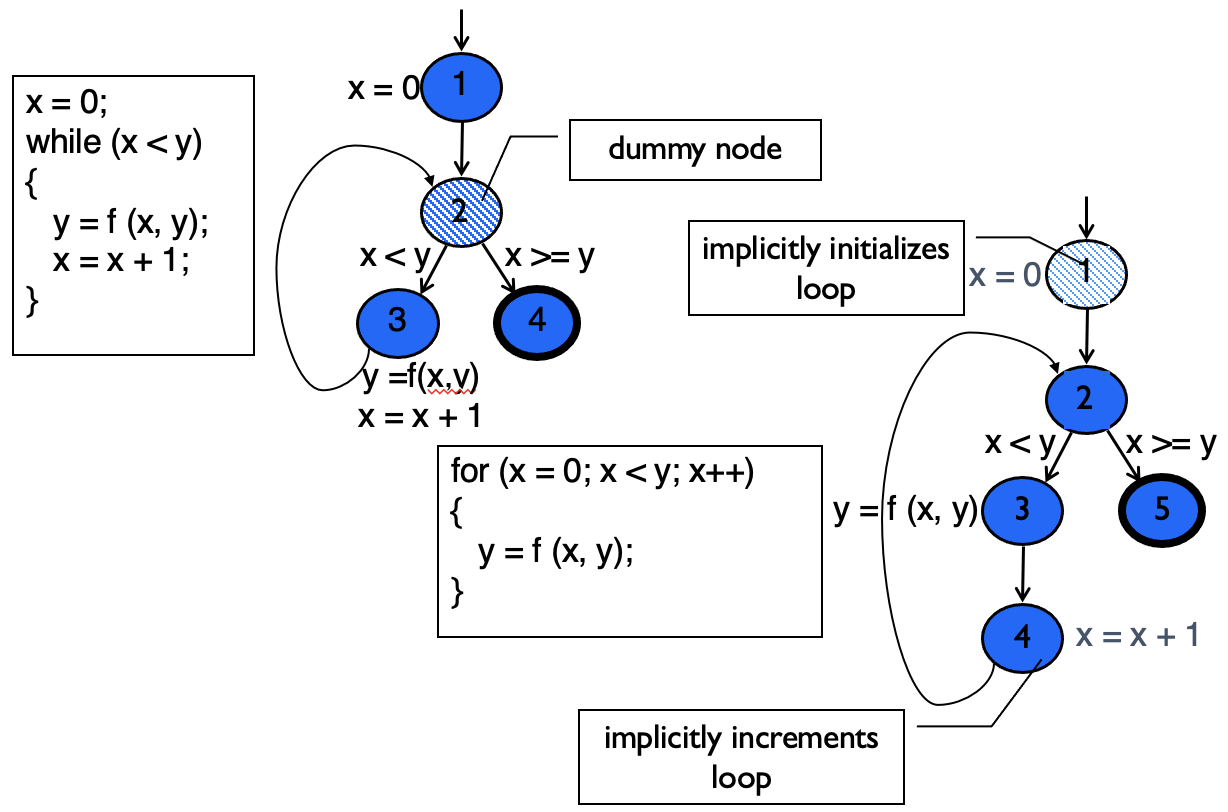
While and For Loops
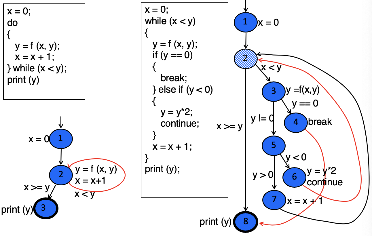
Do Loop, break and continue
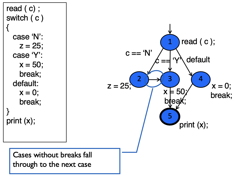
The case (switch) Structure
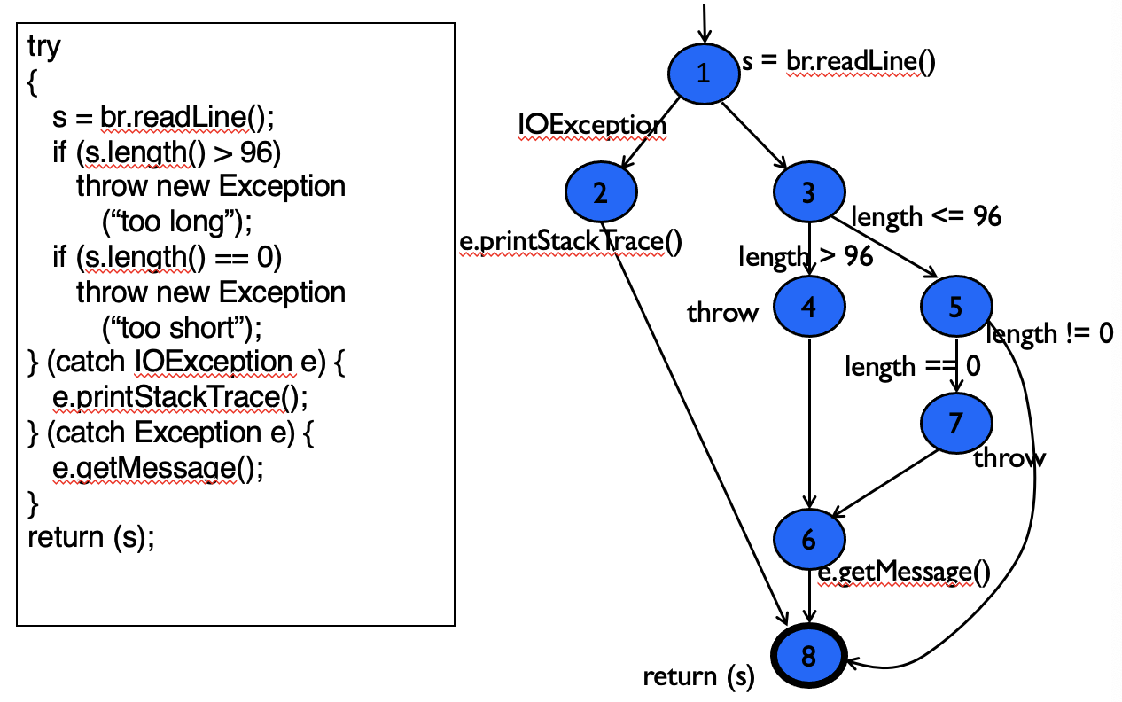
Exceptions (try-catch)
Example Control Flow - Stats
public static void computeStats (int [ ] numbers)
{
     int length = numbers.length;
     double med, var, sd, mean, sum, varsum;

     sum = 0;
     for (int i = 0; i < length; i++)
     {
          sum += numbers [ i ];
     }
     med   = numbers [ length / 2];
     mean = sum / (double) length;

     varsum = 0;
     for (int i = 0; i < length; i++)
     {
          varsum = varsum  + ((numbers [ i ] - mean) * (numbers [ i ] - mean));
     }
     var = varsum / ( length - 1.0 );
     sd  = Math.sqrt ( var );

     System.out.println ("length:                   " + length);
     System.out.println ("mean:                    " + mean);
     System.out.println ("median:                 " + med);
     System.out.println ("variance:                " + var);
     System.out.println ("standard deviation: " + sd);
}
We suggest stopping here and having the students draw the graph themselves. Then show the graph on the next slide to compare their answers.
CFG Exercise:
