MIPS
MIPS use a 32-bit version (while 64-bit version does exist, the theory is the same). his means that the machine instructions will all be 32 bits in length.
MIPS = Millions of instructions per second. IPS Instructions ^6bb171
MIPS Hardware
The following is a pictorial representation of the simplified MIPS Processor and RAM:
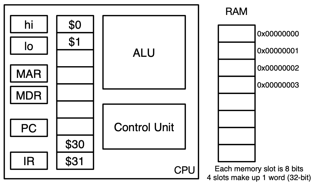
Control Unit: The Control Unit is the brain of the processor. It controls the sequence of instructions to execute, interprets the instructions and the flow of data, contains the processor’s timing unit, and controls signals to and from peripheral devices (not discussed in the course).
Arithmetic Logic Unit (ALU): The ALU performs mathematical operations such as addition, multiplication, logical comparison and decisions requested by the control unit.
General Purpose Registers: Our MIPS processor has 32 so-called “general purpose registers” (labelled 31 in the diagram). Each register holds 32 bits. While these registers are la- beled for general use, we will use some of them to hold specific values at all times, and some of them have special uses dictated by MIPS. In particular, 0 are ignored by MIPS CPUs), 30 as the stack pointer and $31 will store the return address. The need for these will be discussed later.
Program Counter (PC) and Instruction Register (IR): PC and IR are two special 32-bit registers used by the Control Unit in fetching and decoding instructions.
Memory Data Register (MDR) and Memory Address Register (MAR): Data travels to and from registers and memory (RAM as a simplification) through the data bus. Very briefly, when the Control Unit wants to read from a memory address, it stores the address in the MAR. Data is fetched from that address and placed into the MDR from where it is loaded into the appropriate register.
Off-chip memory (RAM): The components discussed above are all physically part of our sim- plified MIPS processor. As you have likely noticed, the processor has access to very limited on-chip memory (in the form of registers). Since registers are physically on the processor, they are incredibly fast, but physical space on the processor comes at a premium. Since programs have bigger memory needs, a real-life processor must therefore also communicate with external memory modules that can hold more data but are slower to access. These include L1/L2 cache, RAM, hard drives, etc. Our simplified processor only communicates with the RAM (shown separately in the diagram above). We will view the RAM as an array of 8-bit (1 byte) slots with addresses starting from 0 at the top and increasing as we go down the array. Since our processor is 32-bits, 4 RAM addresses comprise a single word. We will use hexadecimal representation for memory addresses.
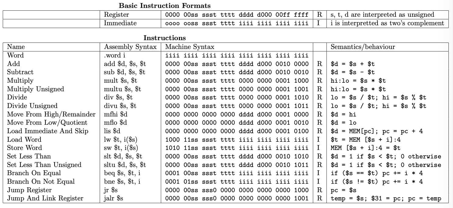
MIPS Machine Language